Beginner's Guide to Designing Printable 3D Models
21 min
- Introduction
- What Makes a 3D Model Printable
- Choose the Right Type of Modeling Before Choosing Software
- Choose a 3D Modeling Tool
- Create Your First 3D Model
- You Don't Always Need to Start From Scratch
- Make Your Model Printable
- Export Your Model for 3D Printing
- Prepare the File for Printing
- Common Beginner Mistakes
- FAQ about Creating 3D Models for Printing
- Conclusion: Creating Print-Ready 3D Models
Key Takeaways
The file is the hard part: A model that looks perfect on screen can fail on the printer if geometry is open, walls are too thin, or units are wrong.
Pick the workflow before the software: Functional parts need parametric CAD, organic models need mesh/sculpting, and simple items suit browser-based tools.
Printability is a design step: Fix non-manifold geometry, close meshes, merge intersecting bodies, and meet minimum wall thickness before exporting.
Export and verify carefully: Choose STL or 3MF appropriately, set correct tolerances, and always confirm scale in millimeters using the slicer preview.
Introduction
Most people assume the hard part of 3D printing is the printer. It isn't. The hard part is the file.
A 3D model designed for rendering may look perfect on screen but fail completely when printed. Floating geometry, surfaces that don't connect, walls too thin to survive the print process, none of that shows up visually in modeling software, but all of it shows up when the printer tries to build the part layer by layer and runs out of instructions for what to do.
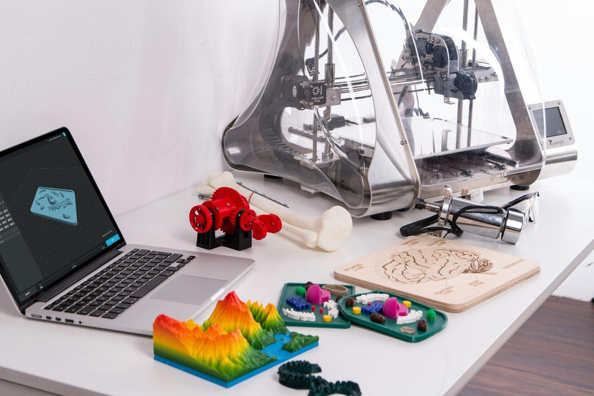
Creating 3D models for printing is a different skill from creating 3D visuals. The model needs to describe a real, physical object with no gaps, no ambiguities, and geometry that can actually be built from the bottom up. That's what this guide covers, not just which software to open, but how to think about the whole process from the start so the file you end up with is something a printer can actually use.
Once your model is ready, you can upload it directly to JLC3DP to get automated file checks, material options, and instant production pricing without any back-and-forth.
- Starting From $0.3 per part · No Minimum Order Quantity
- 24-Hour Lead Time · Up to $123 Welcome Coupons
What Makes a 3D Model Printable
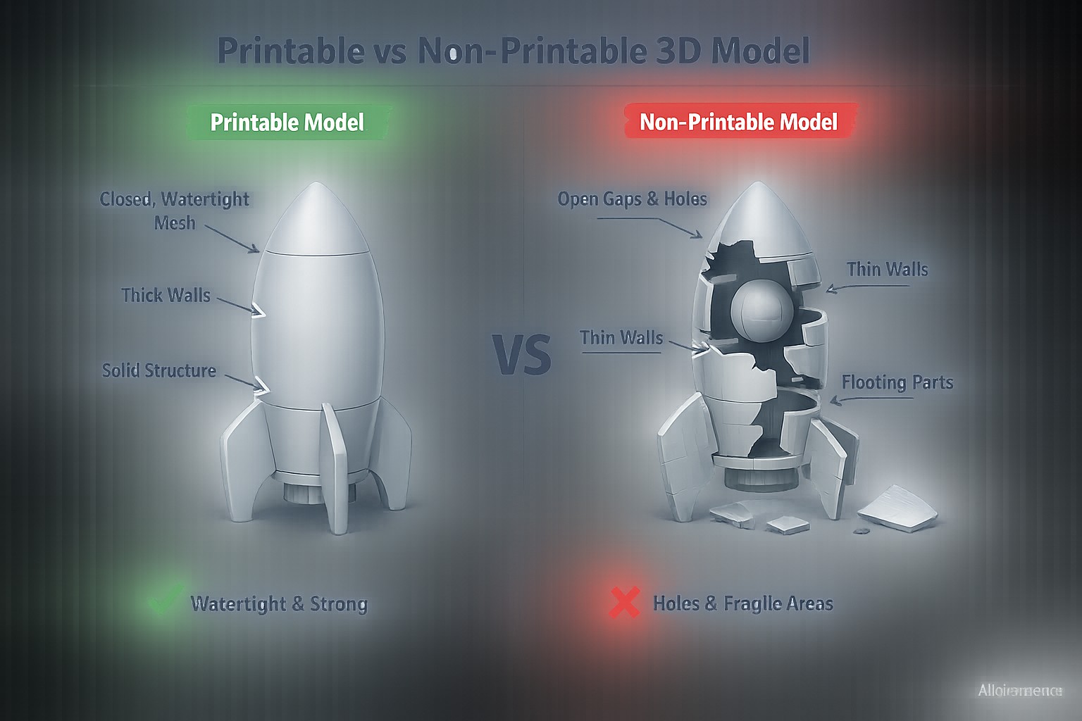
Not every 3D model is a printable 3D model. A model that exists in software is just math, a collection of surfaces or polygons describing a shape. A printer needs more than that. It needs a model that describes a complete, unambiguous solid object with no holes, no impossible geometry, and features thick enough to survive being built in physical material.
Printable vs Non-Printable Models
| Feature | Printable | Non-Printable |
|---|---|---|
| Geometry | Fully closed, completely closed mesh | Open surfaces, gaps, holes in mesh |
| Walls | Above minimum thickness for material | Too thin to print or survive post-processing |
| Shells | Single continuous shell | Multiple disconnected bodies (note: movable parts and multi-material prints like WJP transparent-color combinations can have multiple separate shells) |
| Scale | Correctly set to real-world units | Arbitrary scale or wrong units |
| Intersections | Bodies properly merged | Overlapping geometry that doesn't union |
| Face normal direction | All facing outward consistently | Inverted or inconsistent face normal direction |
Closed Geometry and Completely Closed Meshes
Every surface in your model needs to connect to another surface. No gaps, no missing faces, no surfaces that end without meeting another surface. A model that fails this test confuses slicing software, which needs to calculate the interior of the object to generate infill and shell paths.
Minimum Wall Thickness
Material has physical limits. FDM printing typically needs walls at least 1.2mm thick (around three nozzle widths at 0.4mm). Resin printing can go thinner but still has limits. A wall that exists at 0.3mm in your model might not exist at all in the printed part, or might print so fragile it breaks on removal. Check the wall thickness guidelines for 3D printing before finalizing any thin features.
Print Orientation
The direction a part prints affects surface finish, strength, and support requirements. Features that overhang more than 45 degrees from vertical need support material below them. Designing with orientation in mind from the start, or checking before export, saves a lot of post-processing work.
Note
Many first-time customers optimize their models after seeing support requirements during file review.
Tolerance Basics
Parts that need to fit together or assemble with other components need clearance gaps designed in. Two parts designed to exactly the same dimension won't fit together in the real world because printing adds slight dimensional variation. A 0.5mm clearance gap on mating faces is a typical starting point for 3D printed assemblies.
Choose the Right Type of Modeling Before Choosing Software
This is the decision most beginners skip, and it's the one that causes the most frustration. Different goals require completely different modeling approaches. Picking software first and figuring out what you're making second is backwards, the workflow that creates a functional bracket is fundamentally different from the one that creates a decorative figurine.
Functional Parts
Brackets, enclosures, fixtures, mounts, and mechanical components need precise dimensions. A bracket that holds a motor needs holes at exact positions, walls at calculated thicknesses, and features that match real hardware specifications. This is parametric CAD territory, modeling where every dimension is a number you set deliberately, and changing one value updates the whole model.
If you're designing something that needs to fit existing hardware, mate with another part, or perform a mechanical function, parametric CAD is the workflow for creating 3D printable models in this category. Dimension accuracy matters from the first sketch.
Artistic and Organic Models
Figurines, sculptures, decorative objects, and organic shapes don't have dimension requirements, they have form requirements. The goal is shape, texture, and visual quality rather than precise measurements. Mesh modeling and digital sculpting tools handle this category, where you push and pull geometry like digital clay rather than entering dimension values.
Creating 3D models for printing in this category is more intuitive but requires different attention to printability, organic sculpted models often have floating geometry, non-manifold edges, and mesh errors that need to be cleaned up before printing.
Quick Customization Projects
Keychains with names, custom nameplates, phone accessories, simple holders, these don't require complex modeling skills. Many can be generated from text, imported from vector files, or customized from existing base models with minimal modification. Browser-based tools handle this category efficiently without the learning curve of full CAD software, making it easy to create files for 3D printing in STL or 3MF format.
Decision Guide
- Needs precise dimensions and mechanical function → Parametric CAD
- Organic shape, artistic, or sculptural → Mesh modeling or sculpting
- Simple customization or text-based → Browser-based tool or SVG import
- Not sure → Start with a browser-based parametric tool and move to dedicated software when you hit its limits
Choose a 3D Modeling Tool
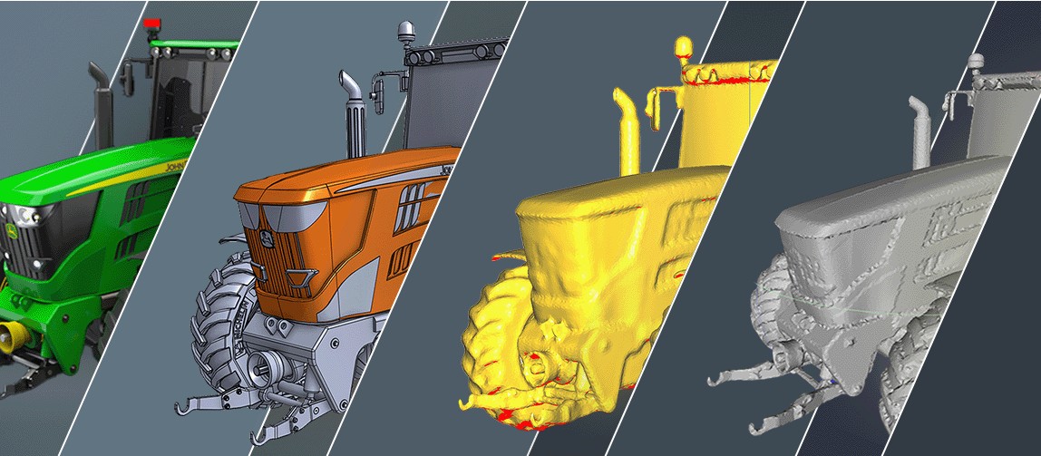
The goal here isn't to review every option, it's to understand the categories so you pick the right type of tool for your goal. Software within each category works similarly. Picking the right category matters more than picking the right brand.
Browser-Based Modeling
Browser-based tools run in a web browser with no installation. They're parametric CAD tools with a simplified interface designed for beginners and intermediate makers. Geometry is built from sketches and dimensions, and the learning curve is shallow enough that most people can create files for 3D printing within a day or two.
Good starting point for: functional parts, enclosures, simple mechanical components, anyone who wants to create 3D printable models without committing to learning professional CAD software.
Parametric CAD
Desktop parametric CAD software is the standard in professional engineering and product development. Models are built from fully dimensioned sketches, with every feature defined by explicit values. Changes propagate through the model, change one dimension and everything that depends on it updates automatically.
Good starting point for: mechanical engineers, product designers, anyone creating parts that need to integrate with existing hardware or meet precise dimensional specifications.
Mesh and Sculpt Modeling
Mesh modeling works with polygon geometry directly, vertices, edges, and faces that define a surface. Sculpting tools let you push, pull, smooth, and carve geometry intuitively. Both approaches produce models that describe surface geometry rather than parametric features, which makes them better for organic shapes and worse for precise mechanical parts.
Good starting point for: character models, figurines, decorative objects, and anyone whose goal is form rather than function.
Which Tool Should Beginners Start With
If you want to create 3D printable models for functional purposes: start with a browser-based parametric tool. When you outgrow it, move to desktop parametric CAD.
If you want to create organic or artistic models: start with a browser-based sculpting tool or a beginner-friendly mesh modeling application.
If you want to customize existing designs or create simple personalized items: a browser-based tool with SVG import capability handles most of these without learning full modeling workflows.
The fastest path to getting a 3D model for printing into a printer is usually the simplest tool that handles your specific goal, not the most powerful software available.
Create Your First 3D Model
1Start With Basic Geometry
Every complex model starts from primitive shapes, boxes, cylinders, spheres. Don't try to build the final shape immediately. Start with a rough block or cylinder that approximates the overall size of the part, then refine from there. This approach keeps the modeling process manageable and makes it easier to maintain correct proportions from the start.
For a simple enclosure: start with a box at the outer dimensions. For a round knob: start with a cylinder at the outer diameter. For a bracket: start with a rectangular block at the widest point.
2Add Dimensions
This is where functional parts diverge from artistic ones. If the part needs to fit something, a screw, a phone, a standard rail, find those dimensions first and build your model around them. Measure the physical object, look up the specification, or find a reference drawing online.
Enter real dimensions from the beginning rather than scaling later. A model built at arbitrary size and scaled to fit introduces rounding errors and unit confusion that cause problems at export. Work in millimeters throughout if you're designing for 3D printing, most slicers and print services work in millimeters and unit mismatches are a common source of incorrectly sized prints.
3Refine Features
Once the basic shape exists at the right size, add the features that make it functional. Holes for fasteners, channels for cables, slots for components, ribs for stiffness. Work from large features to small ones, cut the main pockets before adding the fine details. This keeps the model history manageable and makes editing easier if dimensions change.
Follow the 3D printing design guidelines during this stage rather than after, catching a wall that's too thin or a feature that needs support material while you're still modeling is much faster than fixing it after export.
4Test for Real-World Use
Before finalizing, think through how the part will actually be used. Will it be handled? Does it need to flex? Will hardware be inserted? Will it mate with another part? Run through the assembly sequence mentally, any feature you'd struggle to reach or any dimension that seems marginal is worth addressing in the model rather than discovering in the physical part.
You Don't Always Need to Start From Scratch
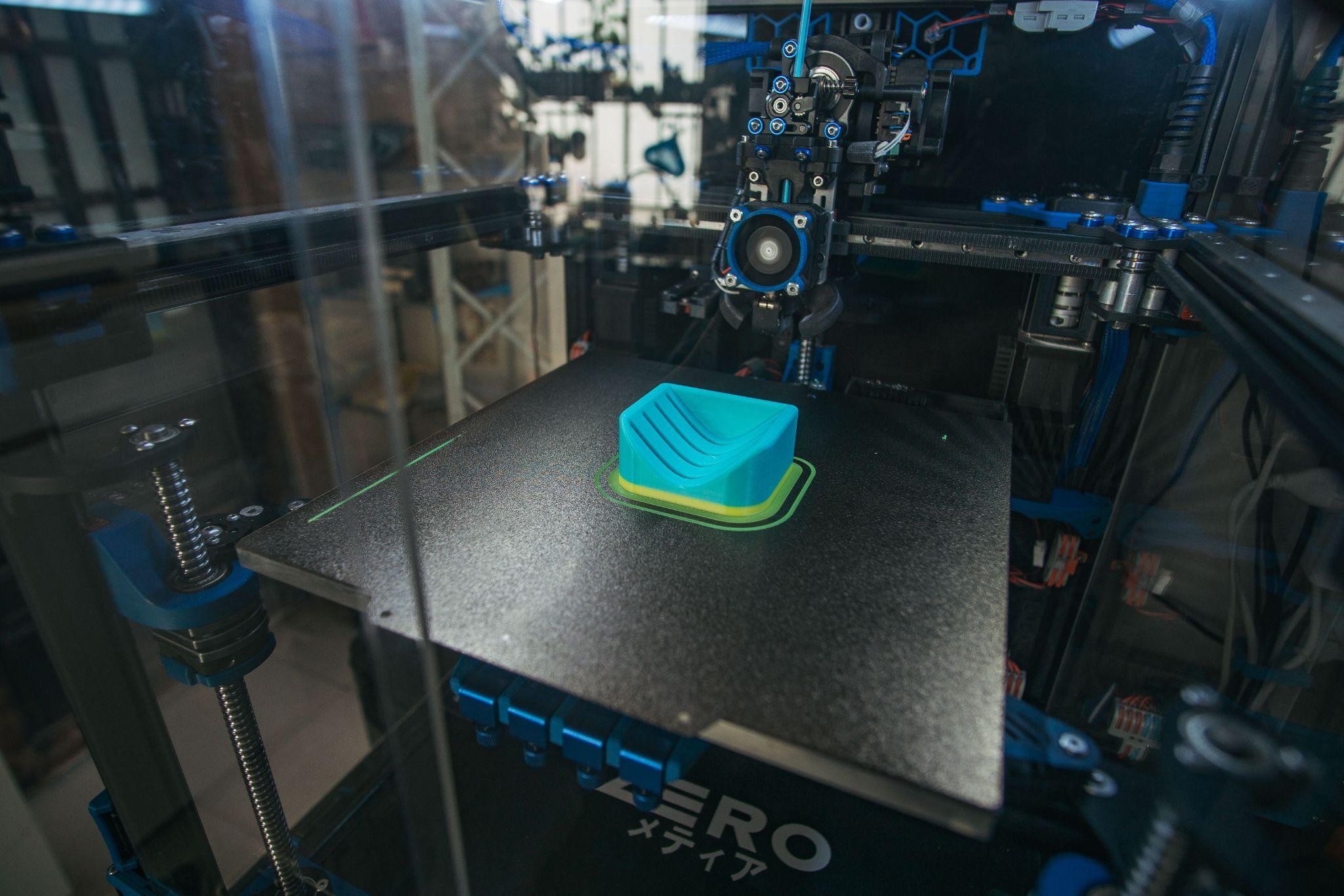
Starting from existing geometry is often faster and produces better results than building from nothing, especially for beginners. The goal is a printable 3D model that works, not a demonstration of modeling skill.
Create From SVG
SVG files are 2D vector graphics, outlines and shapes defined mathematically rather than as pixels. Most parametric CAD tools and many browser-based modeling tools can import SVG files and extrude them into 3D geometry directly. This makes creating 3D models for printing from logos, text, or existing artwork significantly faster than building the same shapes from scratch in 3D.
A nameplate with a company logo: export the logo as SVG, import it into your modeling tool, extrude to the desired thickness, add mounting holes, done. The same workflow that would take an hour of 3D sketching from scratch takes ten minutes using an SVG import.
Customize Existing Designs
Model repositories like Printables, Thingiverse, and Cults3D host millions of existing designs available for download and modification. Finding a base model close to what you need and modifying dimensions, adding features, or combining it with other geometry is often faster than building from zero.
Most parametric CAD tools can import STEP or IGES files from other CAD software. Mesh-based models (STL, OBJ) are harder to edit parametrically but can be modified in mesh editing tools or used as reference geometry for building a new model around an existing shape.
Combine Components
Complex assemblies don't need to be modeled as one piece. Individual components modeled separately and combined in an assembly environment, or imported together in the slicer, keeps each part manageable and makes it easier to modify one component without affecting others. Hinges, snap fits, and multi-part assemblies are usually easier to design as separate parts than as one complex geometry.
Make Your Model Printable
This is the step that determines whether the file you've built can actually be manufactured. A model that looks correct on screen can still fail at this stage if the underlying geometry has issues the visualization doesn't show.
Fix Non-Manifold Geometry
Non-manifold geometry means edges or vertices where the mesh topology is ambiguous, an edge shared by three or more faces, or a vertex where geometry meets in a way that doesn't define a clear inside and outside. Slicing software can't process non-manifold geometry reliably and will either produce errors or generate unpredictable results.
Most mesh repair tools (Meshmixer, Blender's 3D Print Toolbox, online repair services) detect and fix non-manifold geometry automatically. For parametric CAD models exported to STL, non-manifold issues often come from intersecting bodies that weren't merged before export.
Repair Open Meshes
Open meshes have holes, faces missing from what should be a closed surface. Every 3D model for printing needs to be a complete, closed solid. Run mesh analysis before export and repair any open boundaries. Many tools have one-click repair functions that close small holes automatically.
Avoid Thin Walls
Walls thinner than the minimum printable thickness for your chosen material and process either don't print at all or print fragile enough to break during removal. Check minimum wall thickness specifications for the process you're printing with and verify your model meets them.
For FDM printing, a general minimum of 1.2mm for structural walls and 0.8mm for non-structural features is a safe starting point. For SLA, 0.8mm is the recommended minimum, though thinner walls are achievable with careful orientation.
Merge Intersecting Bodies
Two bodies that overlap in a model aren't automatically one solid, they're two separate objects that happen to occupy overlapping space. Slicers handle this inconsistently, sometimes treating the overlap as solid and sometimes as a void. Boolean union operations merge intersecting bodies into a single solid before export, which removes the ambiguity.
Printability Checklist
Before Exporting, Confirm
Before exporting your 3D model for printing, confirm:
- Model is completely closed mesh with no open surfaces
- All walls meet minimum thickness requirements
- Scale is set correctly in real-world units (millimeters)
- All intersecting bodies have been merged
- Model is a single shell or intentional multi-body assembly
- File is ready to export in the correct format
If you want to validate your design before committing to a production run, upload your model to JLC3DP to receive automated file checks, material recommendations, and production-ready feedback, before spending money on prints that might not work.
Export Your Model for 3D Printing
STL vs 3MF
STL is the older and still most widely accepted format for 3D printing. It describes the surface geometry of a model as a mesh of triangles. It works everywhere but carries no information about color, materials, or print settings.
3MF is a newer format developed specifically for 3D printing that stores geometry alongside color, material, and print settings data. Choose 3MF for multi-color models and STL for single-color models based on your needs. When compatibility is uncertain, STL is the safe default. Note: not every printer ecosystem fully supports 3MF. For more detail on when to use each, see the 3D printing file formats guide .
Export Settings
STL export quality is controlled by chord tolerance and angle tolerance settings, these determine how closely the triangle mesh approximates curved surfaces. Too coarse and curved surfaces look faceted in the printed part. Too fine and file size becomes unnecessarily large without visible quality improvement. A chord tolerance of 0.01-0.02mm and angle tolerance of 1-2 degrees covers most printing applications.
Unit and Scale Checks
Before considering the export complete, confirm the file is at the correct scale. Open the exported file in a slicer or viewer and check that the dimensions match what you modeled. Unit mismatches, modeling in inches and exporting as millimeters without conversion, for example, produce parts at wildly wrong sizes that aren't always obvious until the part comes out of the printer at 25x the intended size or 1/25th of it.
If your modeling software allows it, set the export units explicitly to millimeters rather than relying on default settings that may vary between software versions.
Prepare the File for Printing
Slicing
A slicer converts your 3D model into the layer-by-layer instructions a printer executes. It generates the paths the print head follows for every layer, calculates where support material is needed, determines infill pattern and density (FDM-specific parameters), and produces the final file (usually G-code for FDM) the printer reads.
Most slicers are free and relatively intuitive for basic use. The key settings to understand from the start are layer height (finer layers = smoother surface, longer print time), infill density (higher density = stronger part, more material), and shell thickness (how many perimeters form the outer walls).
Supports
Any surface that overhangs more than roughly 45 degrees from vertical needs support material printed beneath it during the build, then removed afterward. Slicers generate supports automatically, but automatic support placement isn't always optimal, supports in deep internal features can be impossible to remove, and dense supports on external surfaces leave marks that need post-processing.
Where possible, orient the model to minimize the surfaces that need support. Designing parts to be self-supporting, chamfers instead of horizontal overhangs, splitting parts that would otherwise need extensive internal supports, reduces post-processing work significantly.
Orientation
Print orientation affects surface finish, strength, support requirements, and print time simultaneously. The bottom surface of a print (touching the build plate) has the best surface finish. Surfaces parallel to the build plate in upper layers have visible layer lines. Strength is highest in the X-Y plane and lowest in the Z direction between layers.
Orient critical surfaces for best finish, structural load axes for best strength, and overall geometry to minimize overhangs, and accept that these three goals often require compromise between them.
Common Beginner Mistakes
Mistakes to Avoid
- Choosing software before choosing workflow: The most common and most avoidable mistake. Spending a week learning parametric CAD to make a figurine, or trying to sculpt a precise mechanical bracket, the wrong tool for the goal makes everything harder. Identify what you're making first, then pick the appropriate category of tool.
- Ignoring printability during modeling: Building a model without checking printability requirements until export produces a rework cycle at the end of the project. Check wall thickness, overhangs, and clearances throughout modeling rather than after the model is "finished."
- Overcomplicated geometry: Beginners often add detail that the printing process can't reproduce and the human eye can't see at print scale. Fine surface textures at 0.1mm feature size, intricate lattices with walls below minimum thickness, extremely complex assemblies with dozens of parts, these create modeling difficulty and print failures without adding visible value. Simplify until the model includes only what the print can actually produce.
- No tolerance planning: Designing two mating parts to the exact same dimension and expecting them to fit together is a reliable way to produce two parts that don't fit together. Build clearance into every mating feature from the start. The specific clearance value depends on the printing process and material, but 0.5mm on mating faces is a reasonable starting point for 3D printed assemblies.
- Exporting wrong units: An STL file has no embedded unit information, a millimeter in software and an inch in software produce identically formatted files that look the same until the slicer interprets them at wildly different scales. Always verify dimensions in the slicer after import.
- Skipping the slicer preview: The slicer preview shows exactly what the printer will build, layer by layer, support structure and all. Skipping it and sending directly to print misses support placement errors, scale problems, orientation issues, and thin features that the slicer has eliminated because they were below minimum printable thickness. The preview is a free quality check that takes two minutes and regularly catches problems that would waste hours of print time.
Note
At JLC3DP, incorrect units are among the most frequent issues detected during automatic file analysis.
FAQ about Creating 3D Models for Printing
Q: How do I create 3D models for printing if I've never used CAD software?
Start with a browser-based parametric tool, they're designed for beginners, run without installation, and have enough capability to create files for 3D printing for most beginner projects. The learning curve from zero to a functional first model is typically a few hours, not weeks.
Q: What file format should I use when I create 3D printable models?
STL works with everything and is the safe default. 3MF is optimized for multi-color models as it carries material and color data, while STL is the universal standard for single-color models. For uploading to a print service, check which formats they accept, most accept both.
Q: How do I know if my 3D model for printing will actually print correctly?
Run it through a slicer and check the preview, the slicer will show you where supports are needed, flag thin walls it can't print, and let you see every layer before committing. Upload to a print service that offers automated file checking for a second opinion on printability before production.
Q: What is the minimum wall thickness when I design models for 3D printing?
For FDM: 1.2mm is a safe minimum for structural walls, 0.8mm for non-structural features. For SLA/DLP/LCD: 0.8mm depending on the specific resin and exposure settings. These minimums vary by material and process, check the specific guidelines for whatever you're printing with.
Q: Do I need expensive software to create printable 3D models?
No. Several capable browser-based and desktop tools are completely free. Professional CAD software has paid versions, but free tiers exist for most major tools and cover the needs of most beginner and intermediate users creating 3D printable models.
Q: Can I modify an existing model instead of building from scratch?
Yes, and for many projects this is the smarter approach. Model repositories have extensive libraries of existing designs available for download and modification. Importing a base model and customizing dimensions or adding features is often faster than building from zero, especially for common object types where good base models already exist.
Conclusion: Creating Print-Ready 3D Models
Designing a printable 3D model is less about mastering one piece of software and more about thinking through the whole process: choose the workflow that matches your goal, model at real dimensions, verify printability before exporting, and always confirm scale in the slicer preview. Get those fundamentals right and the file you hand to a printer, or upload to a service like JLC3DP, will build cleanly the first time.
Keep Learning
How to Edit STL Files: Tools and Techniques That Work
Key Takeaways You can edit STL files without going back to CAD: mesh editors handle scaling, cutting, combining, and sculpting directly on the triangle mesh. STL files carry no feature history, so CAD-style edits (change one hole diameter, thicken one wall) are not possible directly: you either edit the mesh or convert it back to a solid model first. The right STL editor depends on the job: Tinkercad or 3D Builder for quick scaling, Meshmixer for cutting and combining, Blender for sculpting, and FreeC......
Image to STL: Convert Images to STL Online for Free
Key Takeaways You can convert an image to STL — the right method depends on what the image shows: a photo becomes a lithophane relief, a logo becomes an extruded shape, or an object photo becomes an AI-generated mesh. Free online converters handle all three methods in a browser, no software install required — pick one based on your image type, not on a tool's marketing. Lithophanes encode photo brightness as thickness; the result prints in translucent filament and reveals the image under backlight. So......
How to Open STL Files: 4 Free Ways (Online, Windows, Mac)
Key Takeaways The fastest way to open an STL file is to drag it into a free online 3D viewer — no installation, works on any device with a browser. On Windows, the built-in 3D Viewer app ships with Windows 10 but may be missing on recent Windows 11 builds, and Paint 3D left the Microsoft Store in November 2024 — the built-in route is fading. macOS and phones ship with no STL viewer at all; a browser-based viewer covers both without installing anything. STL files carry no units. Always confirm the file......
OrcaSlicer vs Prusa, Bambu & Cura: All Features, Pros & Cons Compared
Orca Slicer is gaining fans fast, but is it really better than the slicers we’ve trusted for years? Whether you're troubleshooting stringy overhangs, dialing in support settings, or optimizing for speed, your slicer software plays a massive role in how your final print turns out. And with the growing popularity of Orca Slicer, especially among Bambu Lab users and tinkerers looking for more control, the question arises: how does it actually stack up against Cura, PrusaSlicer, and Bambu Studio? In this ......
What Is an STL File? Inside the Format Every Slicer Reads
Key Takeaways An STL file describes a 3D shape as a list of triangles — geometry and nothing else. No units, no color, no material, no assembly structure. The format dates to the late 1980s, created for the first stereolithography machines, and it remains the one format practically every slicer reads. STL comes in binary and ASCII variants holding the same mesh; ASCII runs several times larger and has no place in a print workflow. A fully closed shell of triangles. Holes and flipped normals are the de......
How to Repair STL Files: Fix Mesh Errors Before 3D Printing
Key Takeaways STL file repair fixes mesh errors such as holes, non-manifold edges, flipped normals, and duplicate vertices, but it does not correct incorrect dimensions or underlying geometry. Before you repair an STL file, check its dimensions and units. STL files generally do not store explicit unit information, so incorrect scale can make a printable model unusable. A repaired or fully closed STL file is not necessarily printable. Repair only fixes mesh errors — wall thickness, minimum feature size......