How to Design 3D Models for Printing
19 min
- Understand the Difference between Modeling and Designing
- Start With the Printing Process in Mind
- Design Geometry That Can Actually Be Printed
- Design for Tolerances and Fit
- Reduce Supports Through Better Design
- Optimize Models for Different 3D Printing Technologies
- Prepare and Validate the File
- Common Design Mistakes
- FAQ about Printable 3D Model Design
Key Takeaways
Failures start in the file: Most 3D printing problems are design problems, not printer problems, and they can be prevented in CAD.
Design for the process: FDM, SLA, SLS, MJF, and metal printing each impose different constraints on wall thickness, supports, and tolerances.
Plan geometry deliberately: Meet minimum wall thickness, avoid unsupported features, reduce overhangs, and design stable bases.
Tolerances are mandatory: Mating parts need designed-in clearance because 3D printing adds material and features never fit at identical nominal dimensions.
Validate before printing: Check geometry, fix non-manifold errors, verify scale in millimeters, and export at the right resolution.
Introduction
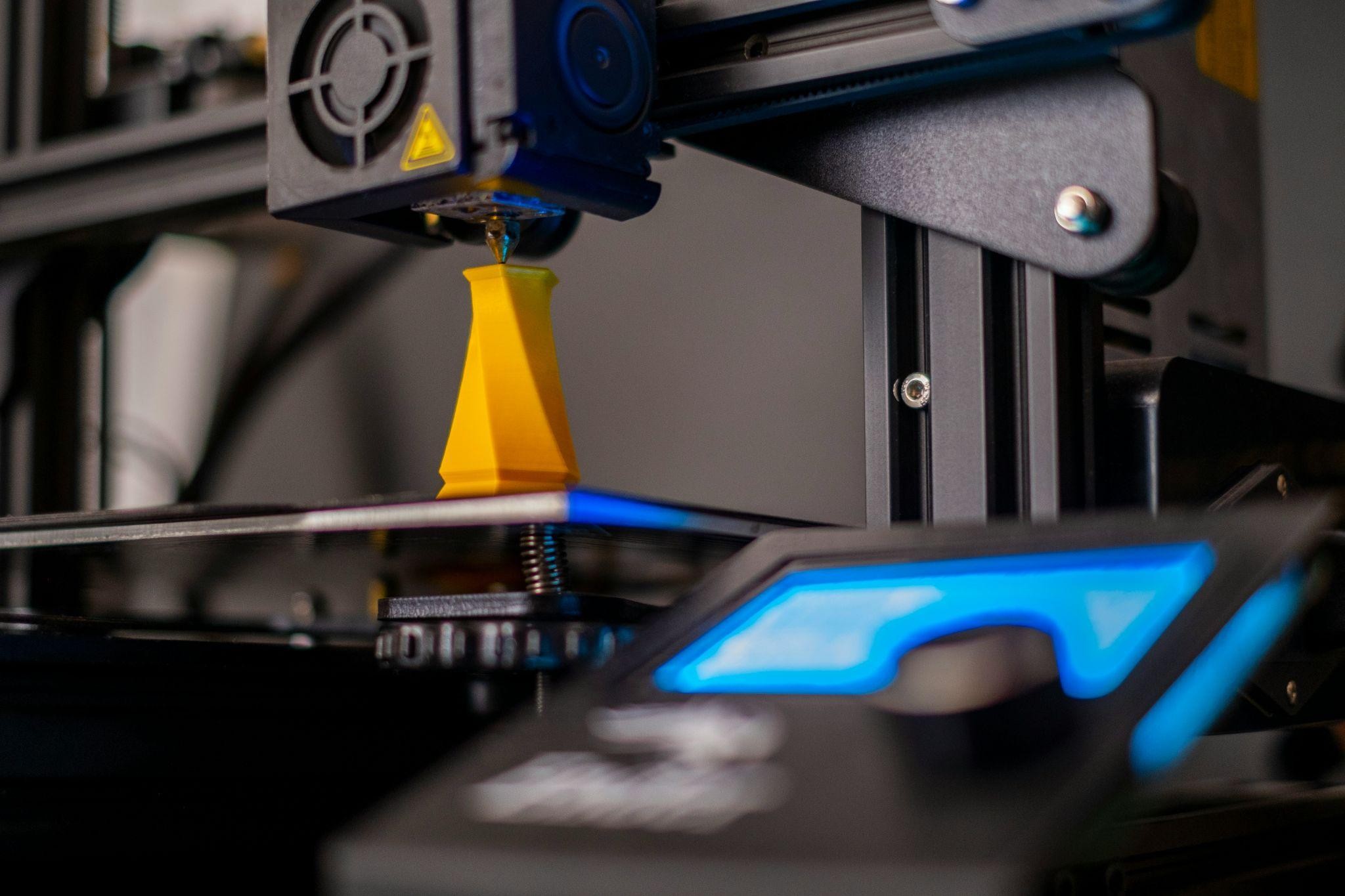
Most 3D printing failures don't start at the printer. They start in the CAD file, sometimes days before anyone tries to print anything. See the recommended design software guide for a breakdown by project type.
A model can look completely correct on screen, proper shape, clean surfaces, the right proportions, and still fail to print because a wall is 0.3mm too thin to survive the process, or because a horizontal feature has nothing below it to build on, or because two bodies overlap in a way that looks solid visually but is geometrically ambiguous to a slicer. These aren't printing problems. They're design problems, and the printer is just the thing that reveals them.
Design for 3D printing is a different discipline from modeling for visualization. The geometry needs to work physically, not just visually. That means understanding the process you're designing for, building geometry that can actually be manufactured, and making decisions during the design phase that determine whether the print succeeds or fails before a single layer is deposited.
This guide focuses on those design principles, applicable across FDM, SLA, SLS, MJF, and metal 3D printing, so the file you send to print is one that actually works. Once your design is ready, uploading it to JLC3DP gives you automated geometry checks and instant pricing before committing to production.
The recommended design software guide covers the modeling workflow that precedes the design principles here.
Understand the Difference between Modeling and Designing
These two words get used interchangeably, but in the context of 3D printing they describe different activities with different success criteria.
Modeling is the act of creating a shape. Designing is the act of creating geometry that can be manufactured to a specification. You can model a perfect-looking object in twenty minutes that would take a week to fix for printing. You can design a simpler object in the same twenty minutes that prints first time.
If your focus is learning the modeling process itself, including software selection and creating printable files, see our guide on How to Create 3D Models for Printing. This article focuses on the design principles that make those models printable.
| Modeling Goal | Design Goal |
|---|---|
| Create the intended shape | Create geometry the process can build |
| Looks correct on screen | Works correctly in physical material |
| Surfaces close and look solid | Geometry is completely closed mesh and manifold |
| Features exist at any size | Features meet minimum printable dimensions |
| Parts fit together visually | Parts fit together with process-appropriate clearance |
| Export any file format | Export in format and resolution appropriate for process |
The shift in mindset is the most important thing in design for 3D printing. Every geometry decision, wall thickness, feature depth, overhang angle, mating clearance, has a manufacturing consequence. Designing means making those decisions deliberately rather than discovering their consequences at the printer.
Start With the Printing Process in Mind
The single most useful question at the start of any 3D printing design project is: what does this part actually need to do? The answer determines the design priorities, which determines the appropriate process, which determines the design constraints you're working within.
Functional Parts
A bracket, fixture, enclosure, or mechanical component needs to perform under load. Design for 3D printing of functional parts prioritizes structural adequacy, sufficient wall thickness to carry the load, orientation that aligns layer boundaries away from the primary stress direction, and tolerances tight enough that the part works in its assembly context. Surface finish is secondary. Getting the geometry and dimensions right is primary.
For functional printable 3D model design, FDM and SLS/MJF/SLM/BJ are the common process choices. FDM for accessible, low-cost functional parts. SLS and MJF for isotropic mechanical properties without layer-direction weakness.
Visual Prototypes
A visual prototype needs to communicate form and proportions accurately. It doesn't carry structural load but may need a fine surface finish, accurate overall dimensions, and clean feature representation. Design for 3D printing of visual prototypes prioritizes surface quality and detail resolution over structural considerations.
SLA and resin-based processes suit visual prototypes, fine layer resolution and smooth as-printed surfaces reduce post-processing. The printable 3D model design focus is on correct proportions, feature detail at the scale of the model, and orientation that puts the best-quality surface where it's most visible.
Production Components
Production components add consistency and material performance to the functional requirements. How to design objects for 3D printing for production use means designing to process capability, tolerances achievable reliably at the process's natural variation, not at the tightest specification the process has ever managed on a single part under optimal conditions. Design to what the process does reliably, not to what it can theoretically achieve.
Design Geometry That Can Actually Be Printed
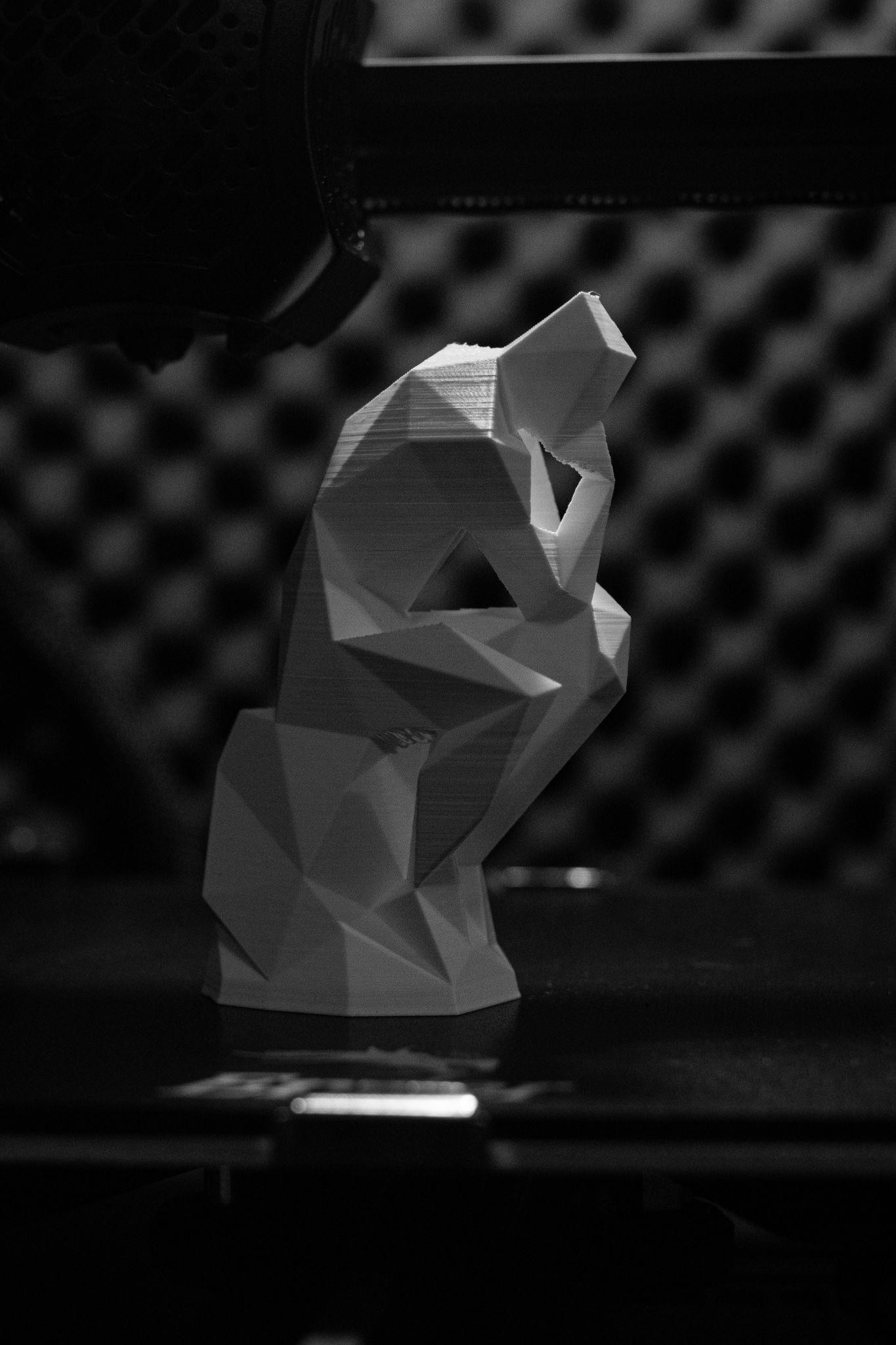
This is the core of how to design 3D print files that work. Each principle below addresses a specific failure mode that causes prints to fail, come out dimensionally wrong, or need excessive post-processing.
1Maintain Minimum Wall Thickness
Note
At JLC3DP, thin walls are one of the most common reasons uploaded files fail automated manufacturability checks. In many cases, increasing the wall thickness slightly is enough to make a model printable without changing its overall design.
Every printing process has a minimum wall thickness below which features either don't print at all or print too fragile to survive handling. Design every wall, rib, pin, and thin feature to meet the minimum for the process you're designing for.
The following minimum wall thicknesses are recommended by JLC3DP engineering for reliable manufacturing: FDM: 1.2 mm; SLA: 0.8 mm (depending on resin and exposure settings); WJP: 1.0 mm; SLS/MJF: 1.0 mm; Metal SLM/Binder Jetting: 1.5 mm. These recommendations are intended to reduce printing risks and improve part success rates. For process-specific guidance, see our wall thickness guidelines for 3D printing.
The failure mode for walls below minimum isn't always a complete missing feature, sometimes the wall prints but is so thin it breaks during support removal or handling. Design with margin above the minimum, not at it.
2Avoid Unsupported Features
Every horizontal surface needs something below it during printing. In FDM, that means the layer below must exist to support the layer above. In SLA printing, the same applies — the model builds upward from the build platform just like FDM. SLS, MJF, and Binder Jetting (BJ) are the exceptions, where surrounding unfused powder acts as natural support for any geometry.
Features that extend horizontally from a wall without support below them, lugs, tabs, horizontal pins, flanges, need either support material, a redesign that angles them into a printable range, or a split into separate parts that can be oriented to avoid the unsupported geometry.
3Reduce Large Overhangs
An overhang is any surface that extends outward from the model without geometry directly below it. In FDM printing, overhangs beyond approximately 45 degrees from vertical print progressively worse, drooping, stringing, or failing entirely, as the angle increases. At 90 degrees (fully horizontal) with no support, most processes can't produce the feature accurately.
The design approach to overhangs: where possible, design at 45 degrees or steeper, add chamfers instead of horizontal ledges, and split parts that have unavoidable horizontal features into orientations where those features become vertical. When supports are genuinely necessary, design the part so supports are accessible for removal rather than buried inside geometry you can't reach.
4Design Stable Bases
A part that can't sit stably on the build plate won't print accurately. Rounded bottoms, pointed bases, and irregular shapes without flat reference surfaces all create first-layer adhesion problems that compound through the entire print. How to design objects for 3D printing with stable bases: add a flat face large enough for the part to sit stably, design with the largest flat face as the natural build orientation, or explicitly design a raft feature into the model rather than relying on the slicer to add one.
Design for Tolerances and Fit
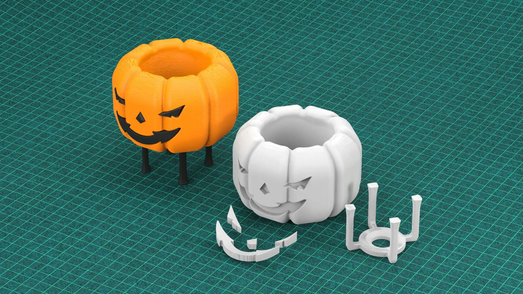
Printable 3D model design for assemblies and mating parts requires explicit tolerance planning. Two parts designed to the same nominal dimension will interfere when printed, 3D printing adds material, and two features at exactly the same dimension occupy the same space and don't fit.
Clearance Between Moving Parts
Moving parts need minimum clearance gaps designed in. Recommended minimum clearances: FDM 0.5mm, SLA 0.5mm, MJF/SLS 0.6mm, SLM/BJ 1.0mm, WJP 1.5mm. These values depend on the specific machine and material; test with your actual process before finalizing clearances on production designs.
Snap Fits
Snap fits are one of the most process-sensitive design features in 3D printing design guidelines. The deflection arm of a snap fit needs to flex and return without breaking, which requires both adequate length for the bending strain to distribute, and sufficient thickness for the feature to survive the deflection. Design cantilever snap fits with an arm length of around five times the arm thickness as a common starting point, although the final geometry should be adjusted based on the material properties and expected deflection. Align the flexure axis with the layer direction that provides the highest interlaminar strength.
Hole Compensation
Holes print undersized in FDM because the material deposited on the inside of a circular path tends to overshoot slightly inward. FDM holes often print slightly undersized (commonly ±0.4mm, depending on machine calibration and nozzle diameter). For precision fits, design holes slightly oversize (0.1-0.2mm larger than nominal) and verify with a test print before committing to final tolerances. Resin and SLS holes are generally more accurate but still benefit from verification on the specific machine being used.
Shrinkage Considerations
Metal 3D printing processes involve significant shrinkage during sintering or cooling, Metal SLM parts may experience dimensional deviations caused by thermal stresses and residual stress relief, and binder jetting metal parts shrink 10-15% during sintering. CAD software or the print service's preparation workflow compensates for this, but the designer needs to know it happens and account for it when designing features with tight tolerances or specific dimensional requirements relative to mating components.
Reduce Supports Through Better Design
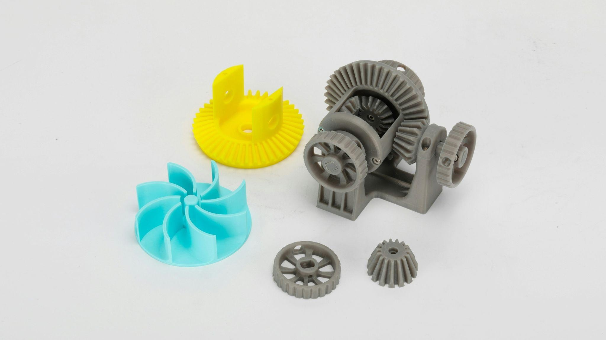
Supports add print time, use material, require post-processing to remove, and often leave surface marks where they contacted the part. How to design 3D print files that minimize support requirements isn't about eliminating them everywhere, it's about making deliberate geometry decisions that reduce where they're needed and ensure they're accessible where they're unavoidable.
Split Complex Models
A single complex model with overhangs in multiple directions often needs supports in places that are impossible or very difficult to remove cleanly. Splitting that model into two or more simpler parts, each of which can be oriented for minimal supports, reduces total support volume, improves surface quality on previously supported faces, and often makes the model easier to print more reliably.
The split-and-assemble approach is an underused design strategy. Two simple parts that glue or snap together after printing are often more practical than one complex part that needs extensive support removal and post-processing.
Use Chamfers Instead of Sharp Angles
A chamfer at 45 degrees is self-supporting in most FDM processes. A horizontal ledge at 90 degrees is not. Replacing horizontal protrusions, ledge features, and sudden outward steps with 45-degree chamfers, where the function allows it, eliminates the need for support on those features without changing what the part does.
Fillets (curved transitions) are structurally superior to chamfers but don't have the same self-supporting property, a curved overhang still overhangs, even if it looks gentler. For support reduction specifically, chamfers are the more useful tool.
Optimize Orientation
The orientation decision is often the most impactful single choice in how to design objects for 3D printing for minimal support. Before finalizing design, look at the model from multiple orientations and identify which one puts the most surfaces in a printable angle range, places functional surfaces away from the build plate where adhesion marks would affect performance, and positions any unavoidable overhangs where supports are accessible for removal.
Orientation can't always compensate for a geometry that fundamentally needs supports in any orientation, that's when splitting the model is the right answer.
Optimize Models for Different 3D Printing Technologies
The design recommendations below are based on JLC3DP's manufacturing capabilities and engineering guidelines. Actual values may vary depending on part geometry, material selection, and production requirements.
| Factor | FDM | SLA | SLS / MJF | Metal SLM | Metal BJ | Full-Color WJP |
|---|---|---|---|---|---|---|
| Minimum wall thickness | 1.2 mm | 0.8 mm | 1.0 mm | 1.5 mm | 1.5 mm | 1.0 mm |
| Supports | Required for overhangs (typically >45–60°) | Required (resin-specific) | Not required | Required; difficult to remove | Not required | Support material required |
| Typical tolerance | ±0.3 mm (≤100 mm); ±0.4% (>100 mm) | ±0.2 mm (≤100 mm); ±0.3% (>100 mm) | ±0.3 mm (≤100 mm); ±0.4% (>100 mm) | ±0.3 mm (≤100 mm); ±0.4% (>100 mm) | ±0.3 mm or ±0.4% (≤50 mm); ±1.3% (>50 mm) | ±0.2mm (≤100 mm); ±0.3% (>100 mm) |
| As-printed surface finish | Visible layer lines | Smooth with fine layer lines | Slightly grainy | Rough; post-processing recommended | Rough; post-processing recommended | Full-color matte finish |
| Hole accuracy | Holes typically print undersized | High | Good | Good (with support optimization) | Allow for sintering shrinkage | Moderate |
| Anisotropy | High (Z-axis weakest) | Moderate | Low (near-isotropic) | Low | Low | Moderate |
| Recommended clearance for moving fits | 0.5 mm | 0.5 mm | 0.6 mm | 1.0 mm (machining recommended) | 1.0 mm | 1.5 mm |
Designing for FDM
FDM is the most process-sensitive technology for design for 3D printing because layer direction creates directional weakness, supports are often difficult to remove cleanly, and hole accuracy requires compensation. The design guidelines for FDM: walls above 1.2mm, overhangs below 45 degrees or chamfered, holes slightly oversized, and critical surfaces oriented away from the build plate. For functional FDM parts, orient so the primary load direction runs in the X-Y plane rather than through the Z-axis layer boundaries.
Designing for SLA
SLA produces fine detail and smooth surfaces but builds inverted from an FDM part, the model hangs downward from the build platform and peels from the resin vat. Supports are required and attach to what is actually the bottom of the finished part. How to design a model for 3D printing in SLA: minimize large flat surfaces parallel to the build plate (they create suction forces on peel that can crack the part), use hollow designs with drainage holes for large solid volumes, and orient to put the best surface quality on the most visible or functional face.
Designing for SLS / MJF
SLS and MJF are the most forgiving processes for printable 3D model design because surrounding unfused powder supports every feature during the build, no support structures, no overhang constraints. The design freedom is genuinely greater than any other common process. The constraints that remain: minimum wall thickness for powder removal from internal channels (typically 1mm channel diameter minimum, with escape holes for enclosed cavities), and understanding that surface finish is somewhat grainy compared to SLA and may need post-processing for sliding contact surfaces.
Designing for Metal 3D Printing (SLM / BJ)
Metal 3D printing design guidelines are the most demanding of any process category. SLM (selective laser melting) fuses metal powder with a high-power laser and builds with support structures required for overhangs, but metal supports are harder to remove than polymer supports and often require machining. Design for SLM: minimize overhangs, design support access for removal, use radii rather than sharp internal corners (stress concentration in metal is a structural concern, not just a cosmetic one), and design wall thicknesses above 1mm for reliable quality.
Binder jetting (BJ) metal printing skips the laser sintering step during printing but sinters the finished green part in a furnace, which causes 10-15% isotropic shrinkage. The print service applies a scale factor to compensate, but tight tolerances on metal BJ parts often require post-process machining of critical features. How to design 3d objects for printing in metal BJ: add machining stock on precision features, avoid thin features that won't survive sintering shrinkage stresses, and consult the JLC3DP CAD design guide for process-specific requirements.
Prepare and Validate the File
Check Geometry
A model has no gaps, no missing faces, and no surfaces that don't connect to adjacent surfaces. Every edge is shared by exactly two faces. Run geometry analysis in your modeling software or in a dedicated mesh repair tool before export.
Fix Non-Manifold Errors
Non-manifold geometry means edges shared by more than two faces, or vertices where the mesh topology is ambiguous. These break slicing algorithms. Fix non-manifold edges by identifying where geometry overlaps without merging, where faces share an edge but are separated by a gap at the vertices, or where boolean operations left geometry artifacts. Most mesh repair tools fix simple non-manifold errors automatically, complex cases require manual geometry correction.
Verify Scale and Units
Export in millimeters and verify dimensions in the slicer after import. Software units don't transfer to STL files, a model built in inches and exported as STL without unit conversion arrives in the slicer at 25.4x the intended size. Check at least one dimension in the slicer before sending to print. See the STL file generation guide for export settings by software.
Export STL, OBJ, or 3MF
STL is the most universally accepted format. 3MF stores color and print settings data, making it suitable for multi-color models. STL is the universal format for single-color models. OBJ is common for organic mesh models from sculpting software. For production uploads, STL at fine mesh resolution (chord tolerance 0.01-0.02mm, angle tolerance 1-2 degrees) covers most requirements without generating unnecessarily large files.
Common Design Mistakes
| Mistake | What Happens | Fix |
|---|---|---|
| Walls below minimum thickness | Feature doesn't print or breaks on removal | Check minimum wall thickness for your process; add material |
| Floating geometry | Slicer errors or missing features in print | Ensure all geometry connects to the main body |
| Excessive fine detail | Detail too small for process resolution, just adds file size | Remove or simplify features smaller than process resolution |
| No tolerance planning | Mating parts don't fit; assemblies won't close | Add clearance gaps appropriate to process at every mating interface |
| Ignoring print orientation | Wrong surfaces get supports; weak layer direction under load | Orient before finalizing design; split if no good orientation exists |
| Exporting wrong units | Part prints at 25x or 1/25x intended size | Verify dimensions in slicer after every export |
| Unsupported horizontal features | Drooping, stringing, or missing features | Chamfer to 45°, split the model, or accept and plan support removal |
| No drainage holes in hollow SLA parts | Uncured resin trapped inside causes cracking | Add 2-4mm minimum drainage holes to all enclosed volumes |
FAQ about Printable 3D Model Design
Q: What is the best way to design for 3D printing?
Start with the process constraints for the technology you're printing with, then build geometry that works within those constraints rather than adapting a finished design afterward. Wall thickness, overhang angles, tolerances, and orientation all need to be considered during design, not after.
Q: How thick should walls be?
FDM: 1.2mm, SLA: 0.8mm, MJF/SLS: 1.0mm, BJ/SLM: 1.5mm, WJP: 1.0mm minimum. These are minimums; design above them where function allows, and always verify with your specific print service for their process-specific guidelines.
Q: How do I avoid supports when designing for 3D printing?
Design overhangs at 45 degrees or less from vertical, use chamfers instead of horizontal ledges, split complex models into simpler parts each of which can be oriented without overhangs, and check orientation before finalizing the design. For SLS and MJF, supports aren't needed at all, which is a significant design freedom advantage of those processes.
Q: What tolerance should I leave between mating parts?
FDM: 0.5mm, SLA: 0.5mm, MJF/SLS: 0.6mm, SLM/BJ: 1.0mm, WJP: 1.5mm minimum clearance between moving parts. Test with your specific process before finalizing production clearances; machine-to-machine variation is real and these values are starting points, not absolutes.
Q: Is CAD required to design 3D models for printing?
CAD is the standard for functional and precision parts. For organic and artistic models, mesh modeling and sculpting tools are more appropriate. For simple customization, browser-based tools without full CAD capability work for many projects. The right tool depends on what the part needs to do.
Conclusion: Designing Print-Ready 3D Models
Designing for 3D printing means thinking like the process from the first sketch: know what the part must do, pick the technology that fits, and build geometry that respects wall thickness, overhangs, tolerances, and orientation. Validate the file, confirm the scale, and export at the right resolution. Get these design decisions right and your model, whether printed in-house or uploaded to a service like JLC3DP, will manufacture reliably instead of revealing hidden problems layer by layer.
Keep Learning
How to Edit STL Files: Tools and Techniques That Work
Key Takeaways You can edit STL files without going back to CAD: mesh editors handle scaling, cutting, combining, and sculpting directly on the triangle mesh. STL files carry no feature history, so CAD-style edits (change one hole diameter, thicken one wall) are not possible directly: you either edit the mesh or convert it back to a solid model first. The right STL editor depends on the job: Tinkercad or 3D Builder for quick scaling, Meshmixer for cutting and combining, Blender for sculpting, and FreeC......
Image to STL: Convert Images to STL Online for Free
Key Takeaways You can convert an image to STL — the right method depends on what the image shows: a photo becomes a lithophane relief, a logo becomes an extruded shape, or an object photo becomes an AI-generated mesh. Free online converters handle all three methods in a browser, no software install required — pick one based on your image type, not on a tool's marketing. Lithophanes encode photo brightness as thickness; the result prints in translucent filament and reveals the image under backlight. So......
How to Open STL Files: 4 Free Ways (Online, Windows, Mac)
Key Takeaways The fastest way to open an STL file is to drag it into a free online 3D viewer — no installation, works on any device with a browser. On Windows, the built-in 3D Viewer app ships with Windows 10 but may be missing on recent Windows 11 builds, and Paint 3D left the Microsoft Store in November 2024 — the built-in route is fading. macOS and phones ship with no STL viewer at all; a browser-based viewer covers both without installing anything. STL files carry no units. Always confirm the file......
OrcaSlicer vs Prusa, Bambu & Cura: All Features, Pros & Cons Compared
Orca Slicer is gaining fans fast, but is it really better than the slicers we’ve trusted for years? Whether you're troubleshooting stringy overhangs, dialing in support settings, or optimizing for speed, your slicer software plays a massive role in how your final print turns out. And with the growing popularity of Orca Slicer, especially among Bambu Lab users and tinkerers looking for more control, the question arises: how does it actually stack up against Cura, PrusaSlicer, and Bambu Studio? In this ......
What Is an STL File? Inside the Format Every Slicer Reads
Key Takeaways An STL file describes a 3D shape as a list of triangles — geometry and nothing else. No units, no color, no material, no assembly structure. The format dates to the late 1980s, created for the first stereolithography machines, and it remains the one format practically every slicer reads. STL comes in binary and ASCII variants holding the same mesh; ASCII runs several times larger and has no place in a print workflow. A fully closed shell of triangles. Holes and flipped normals are the de......
How to Repair STL Files: Fix Mesh Errors Before 3D Printing
Key Takeaways STL file repair fixes mesh errors such as holes, non-manifold edges, flipped normals, and duplicate vertices, but it does not correct incorrect dimensions or underlying geometry. Before you repair an STL file, check its dimensions and units. STL files generally do not store explicit unit information, so incorrect scale can make a printable model unusable. A repaired or fully closed STL file is not necessarily printable. Repair only fixes mesh errors — wall thickness, minimum feature size......