Design for Additive Manufacturing: A Practical DfAM Guide
16 min
- What Does DfAM Stand For?
- DfAM vs DFM vs Design for Machining: What Actually Changes?
- Why Design for Additive Manufacturing? The 4 Things Only AM Can Do
- How Do You Design for Additive Manufacturing? 12 Core Rules
- Anisotropy: How Build Orientation Affects Strength
- DfAM by Process: FDM, SLA, SLS, MJF and Metal
- DfAM in Product Design and Engineering Practice
- FAQ about Design for Additive Manufacturing
- Conclusion: Design for Additive Manufacturing
Key Takeaways
DfAM is not DFM: Design for additive manufacturing focuses on exploiting AM's geometric freedom rather than simply simplifying parts.
Build orientation matters: Orientation affects strength, surface finish, supports, thermal distortion, and overall cost.
Design for the process: Wall thickness, overhangs, holes, clearances, and tolerances must match the specific AM technology and material.
Complexity can reduce cost: Part consolidation, lattices, and internal channels can deliver value that machining and molding cannot.
Validate before production: Use process-specific design rules and test coupons to verify critical fits, dimensions, and mechanical performance.
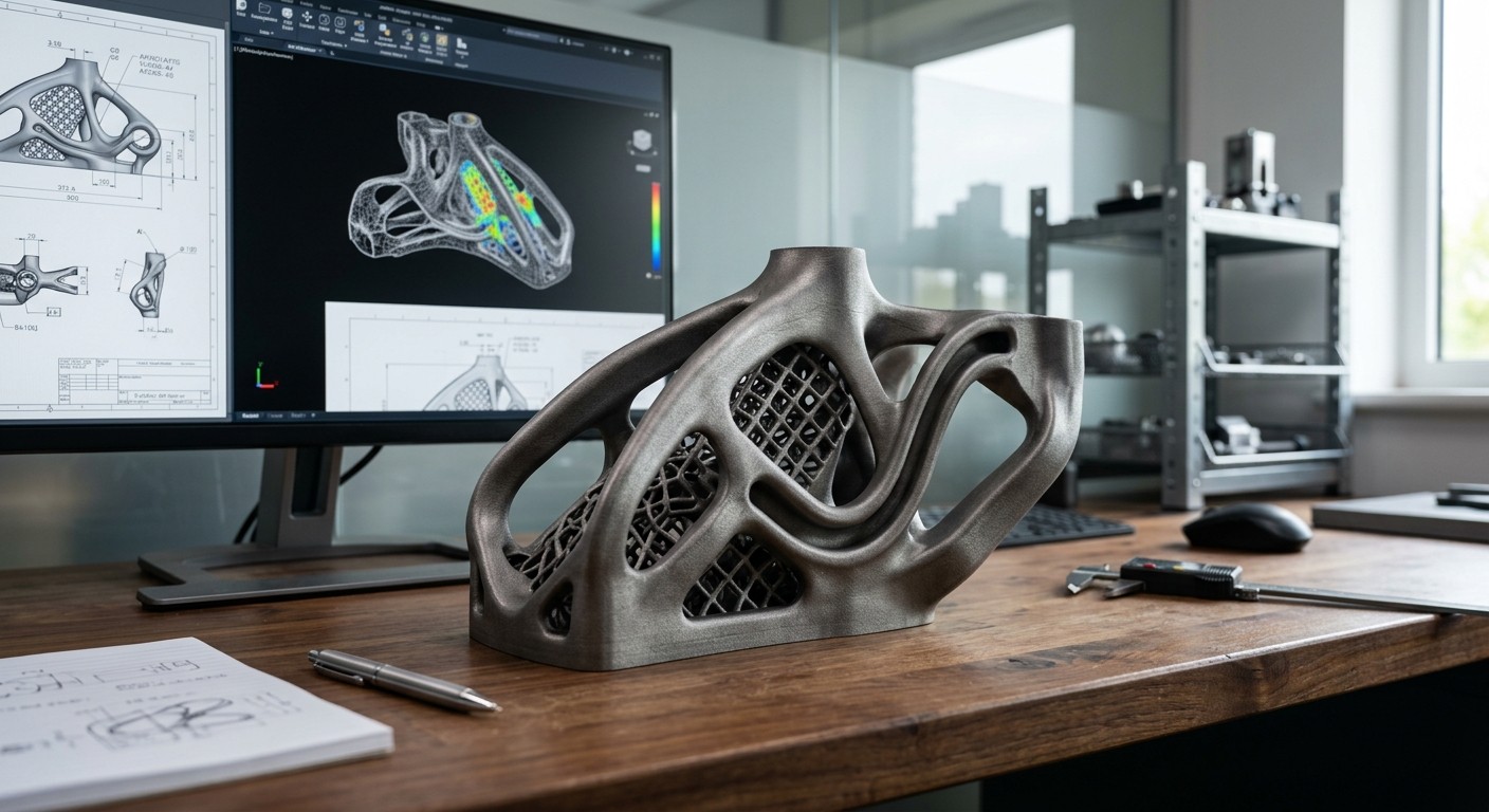
DfAM is designing parts to exploit what 3D printing can do, not just to survive it. Unlike DFM, DfAM lets you add complexity for less cost, but charges you for height, support and Z-strength.
Every rule below follows from that trade: additive design rewards geometric freedom and penalizes build height, while traditional design for manufacturing does the opposite. This guide walks through what design for additive manufacturing means in practice, how it differs from DFM, and the numeric rules engineers use to design for additive manufacturing across FDM, SLA, SLS, MJF, and metal processes.
What Does DfAM Stand For?
Design for additive manufacturing (DfAM) is the engineering practice of designing parts specifically for AM processes. It considers build orientation, wall thickness, support requirements, anisotropy, tolerances, material behavior, post-processing, and production economics to improve manufacturability, part performance, cost, and lead time.
Note
DFAM also refers to the Moog DFAM drum machine (Drummer From Another Mother), a popular analog percussion synthesizer. This article covers Design for Additive Manufacturing (DfAM), the engineering discipline, not the music gear.
DfAM stands for Design for Additive Manufacturing, written with a lowercase "f" (DfAM) specifically to distinguish it from DFM, Design for Manufacturing. Under the design for additive manufacturing abbreviation convention used across engineering literature, the lowercase "f" signals a process-specific design discipline rather than the general manufacturing term. Some sources render the design for additive manufacturing dfam definition as "additive manufacturing design," but the underlying concept is the same: designing geometry that only additive processes can produce economically.
DfAM is not to be confused with:
- DFM (Design for Manufacturing), rules for injection molding, casting, and machining
- Moog DFAM, the drum machine referenced above
Industry adoption of DfAM is a growing standard in aerospace (Boeing, GE), medical devices (Stryker, Zimmer Biomet), and automotive, where weight reduction and part consolidation deliver measurable performance gains. When engineers ask what DfAM stand for in a production context, the honest answer is: a design methodology, not a single tool, one that changes which rules apply depending on the process.
DfAM vs DFM vs Design for Machining: What Actually Changes?
The reason additive design needs its own rulebook is that AM inverts several DFM assumptions. A wall thickness rule that protects an injection-molded part from sink marks can be actively wrong for a 3D-printed one.
| Design Rule | Injection Molding (DFM) | CNC Machining | Additive (DfAM) |
|---|---|---|---|
| Wall thickness | Must be UNIFORM (2-4mm) | Minimum dictated by tool deflection | Can vary freely (0.4mm min for FDM) |
| Internal cavities | Require slides / cores $$$ | Impossible without 5-axis or EDM | No cost penalty |
| Complexity cost | Exponential with features | Linear with machine time | Often much less sensitive to geometric complexity than tooling-based manufacturing |
| Undercuts | Require side-actions / lifters | Require T-slot cutters / repositioning | Free (within overhang limits) |
| Directional strength | Near-isotropic | Isotropic (material-dependent) | Anisotropic: Z-axis weakest |
| Draft angles | Required (1-3 degrees) | Not applicable | Not required |
| Part consolidation | Limited by mold complexity | Assembly required for complex parts | Anything printable = one part |
This is the core distinction behind design for additive manufacturing vs design for machining: DFM removes cost by simplifying geometry, while DfAM removes cost by consolidating it. For a deeper breakdown of injection-molding rules, see our DFM pillar guide.
Why Design for Additive Manufacturing? The 4 Things Only AM Can Do
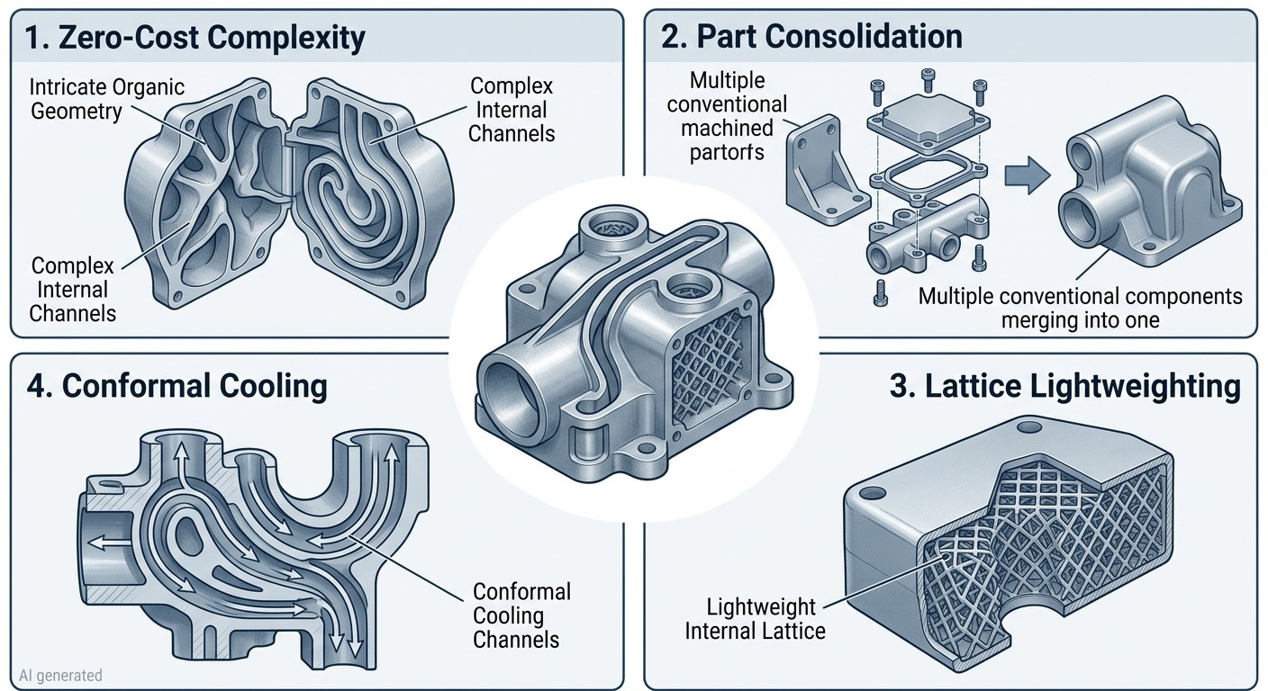
Designing for additive manufacturing only pays off when a part actually uses capabilities that subtractive and formative processes can't touch. Four capabilities carry most of that value, and each has a quantified benefit engineers can point to.
1Low-cost geometric complexity
Additive manufacturing can produce complex geometries, internal channels, lattices, and consolidated assemblies with much less tooling penalty than injection molding or machining. However, complexity can still increase build time, support requirements, post-processing, and inspection effort.
2Part consolidation
GE Aviation's LEAP fuel nozzle is a well-known example of DfAM-driven part consolidation: a 20-part welded and brazed assembly was redesigned as a single additively manufactured component, cutting weight by 25% while making the part roughly five times more durable than the assembly it replaced. GE has since applied the same consolidation logic to its Catalyst turboprop engine, reducing an 855-part assembly down to 12 parts.
3Lattice lightweighting
Replacing solid regions with engineered lattice structures typically delivers a 40–60% weight reduction versus a solid equivalent, with stiffness tunable by adjusting strut diameter and unit-cell type, a trade-off that has no equivalent in molded or machined design.
4Conformal cooling
Injection-mold tooling with curved internal cooling channels, geometry that's impossible to drill or machine, is a widely cited use of metal AM for tooling inserts, with published studies reporting cycle-time reductions in the range of 20–40% depending on part geometry and channel design.
How Do You Design for Additive Manufacturing? 12 Core Rules
This is the operational core of additive design: 12 practical rules covering build orientation, supports, feature size, tolerances, packing, post-processing, and validation.
1Design around build orientation and anisotropy
Mechanical properties can vary with build orientation, especially in layer-based processes such as FDM and metal laser powder bed fusion. Orient critical load paths to use the strongest and most predictable material direction, while considering surface finish, support requirements, build height, and thermal effects at the same time. For critical structural parts, use material- and process-specific mechanical data rather than assuming a universal Z-axis strength penalty.
2Respect overhang limits, the 45-degree rule
See the process-specific thresholds below; exceeding them without support can result in drooping, deformation, or failed layers.
3Minimize support structures
Supports can materially increase material consumption, print time, and post-processing effort, especially for SLA, FDM, and metal AM.
4Design for thermal and residual-stress effects
Thermal gradients during printing can cause residual stress, distortion, warping, and—in metal AM—cracking or support failure. Reduce these risks by avoiding large unsupported cross-sections, minimizing abrupt changes in section thickness, using appropriate build orientation and supports, and considering stress-relief or heat-treatment requirements for metal parts. For dimensionally critical components, allow for process-specific distortion and validate the final geometry after post-processing.
5Design for the minimum feature size of your process
Minimum wall thickness varies by process and material. Use the process-specific values in the table below as starting points.
6Avoid large flat surfaces on the build plate
Warping risk rises with footprint area, especially for FDM and unsintered SLS regions; break up large flats with ribs or a curved base.
7Use fillets at sharp internal corners
Stress concentrations at 90-degree internal corners are real in printed polymers and metals alike; a minimum 0.5–1mm radius is a reasonable default across processes.
8Design clearance gaps for assembled or moving parts
Minimum clearance is roughly 0.3mm for FDM, 0.2mm for SLA, 0.15mm for SLS, and 0.2mm for MJF.
9Optimize for build volume packing
Print cost scales primarily with Z-height (time) and volume (material), so nesting parts to minimize height matters more than minimizing footprint.
10Consider post-processing in the design phase
Support removal, sanding, dyeing, and vapor smoothing all add design constraints, escape holes, accessible support interfaces, and wall thickness margin should be planned up front.
11Design escape holes for hollow or powder-bed parts
SLS and MJF trap unfused powder inside closed cavities without drain holes; a minimum 3–5mm diameter hole is the standard recommendation.
12Validate with a test coupon before a full build
A small tensile or fit-check coupon in the actual print orientation catches anisotropy and tolerance issues before committing a full build to a design.
DfAM Quick Reference: Process-Specific Design Considerations
Note
These are general design considerations rather than guaranteed manufacturing limits. Actual capabilities depend on material, machine, geometry, orientation, and process parameters.
Not sure which additive manufacturing process fits your design? Upload your CAD file to compare suitable processes, materials, and pricing.
| Parameter | FDM | SLA | SLS | MJF | Metal(SLM/BJ) |
|---|---|---|---|---|---|
| Min. wall | 0.8–1.2 mm | 0.5 mm | 0.7 mm | 0.5 mm | 0.3–0.5 mm |
| Accuracy | ±0.2–0.5 mm | ±0.1 mm | ±0.2 mm | ±0.2 mm | ±0.05–0.1 mm |
| Min. hole | 1.0 mm | 0.5 mm | 0.8 mm | 0.5 mm | 0.5 mm |
| Clearance | 0.3 mm | 0.2 mm | 0.15 mm | 0.2 mm | 0.1 mm |
| Overhang | ~45° | ~45° | Self-supporting | Self-supporting | ~45°* |
| Surface finish (Ra) | 10–25 µm | 1–5 µm | 8–15 µm | 5–10 µm | 5–15 µm |
| Cost drivers | Material + print time | Resin + print time + supports | Material + build time | Material + build time | Material + build + debinding/sintering |
Orientation, Supports and the 45-Degree Rule
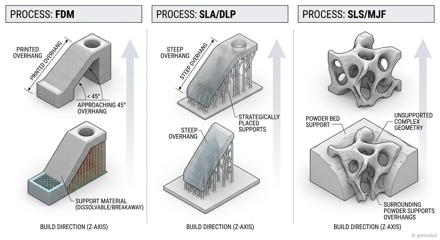
Overhang tolerance is process-specific, and getting it wrong is the single most common cause of failed or ugly prints:
- FDM: Surfaces steeper than ~45° from horizontal (i.e., within ~45° of vertical) generally selfsupport: beyond that, add supports; short bridging spans (under roughly 10mm) can print unsupported.
- SLA/DLP: Overhangs beyond about 45 degrees typically need supports, with minimum support-tip contact around 0.3–0.5mm diameter.
- SLS / MJF: Both are self-supporting because the surrounding powder bed acts as support, so there's effectively no overhang limit, though minimum unsupported wall thickness still applies (roughly 0.7mm for SLS, 0.5mm for MJF).
Anisotropy: How Build Orientation Affects Strength
Every AM process produces a part that's mechanically directional, because layers bond to each other more weakly than the material bonds within a single layer. Manufacturer ASTM D638 test data makes the size of that penalty explicit:
| Process / Material | In-Plane Tensile Strength | Z / Through-Build Tensile Strength | Z / In-Plane Ratio | Test Standard |
|---|---|---|---|---|
| FDM — Stratasys ABS-M30 | 28.1 MPa* | 26.8 MPa* | 95.4% | ASTM D638 |
| SLA — Formlabs Clear Resin | Orientation-dependent data; no single XY/Z pair reported | Orientation-dependent data; no single XY/Z pair reported | No single ratio | ASTM D638 |
| SLS — EOS PA 2200 | 48 MPa | 42 MPa | 87.5% | ISO 527-1/-2† |
| MJF — HP 3D High Reusability PA 12 | 49 MPa | 45 MPa | 91.8% | ASTM D638 |
The strength of a 3D printed part can depend on build orientation, but the size of that effect varies substantially by printing process, material, and process parameters. The most defensible way to show the difference is to use manufacturer-published tensile data and identify the test standard and specimen orientation rather than assigning a universal Z-axis penalty to each technology.
Note
Stratasys reports these as XZ and ZX orientations, respectively, rather than a simple XY/Z pair. The values are therefore not a literal XY-vs-Z comparison, and the ratio should be presented as an orientation comparison, not a universal ABS anisotropy ratio. Stratasys reports 28.1 MPa strength at break for XZ and 26.8 MPa for ZX under its F900/T16 test configuration, using ASTM D638.
EOS reports PA 2200 tensile strength of 48 MPa in X and Y and 42 MPa in Z, but uses ISO 527-1/-2, not ASTM D638. It should therefore be treated as supporting orientation data rather than as ASTM D638 data.
Formlabs' SLA study is particularly useful because it actually tested ASTM D638 Type IV specimens at multiple build angles from 0° to 90°. Rather than presenting a fabricated XY/Z ratio, the study found SLA tensile strength to be relatively insensitive to build orientation under its tested conditions.
Z-axis strength isn't a fixed percentage of in-plane strength across 3D printing technologies. FDM can show significant orientation dependence depending on material and print parameters, while powder-bed processes such as SLS and MJF can produce much smaller differences between in-plane and Z directions. SLA can also show relatively isotropic tensile behavior when the resin is properly processed and post-cured. The actual values depend on the specific material, machine, process parameters, specimen orientation, and test method.
DfAM by Process: FDM, SLA, SLS, MJF and Metal
Different additive manufacturing processes have different design constraints, including minimum wall thickness, feature size, tolerances, overhang behavior, and post-processing requirements.
| Requirement | FDM | SLA | SLS | MJF | Metal AM |
|---|---|---|---|---|---|
| Supports | Usually required | Usually required | Not typically required | Not typically required | Often required |
| Overhangs | Process-dependent | Process-dependent | Generally self-supporting | Generally self-supporting | Process-dependent |
| Anisotropy | Material/process dependent | Usually low–moderate | Generally low | Generally low | Material/process dependent |
| Key constraint | Overhangs, warping | Supports, orientation | Thin walls, heat buildup | Thin walls, heat buildup | Supports, thermal stress |
| Best suited for | Low-cost prototypes | Fine details & smooth surfaces | Functional nylon parts | Production polymer parts | High-performance metal parts |
Metal processes may require supports depending on geometry and process. Metal BJ and SLM have different design constraints. Metal BJ generally reduces the need for conventional support structures because parts are supported by surrounding powder during printing, but debinding and sintering introduce shrinkage and distortion considerations. SLM often requires support structures for overhangs and thermal management, making build orientation an important part of DfAM.
Note
These are typical design guidelines, not guaranteed process limits. Actual capabilities vary by machine, material, geometry, and supplier. For process-specific design rules, see our FDM design guide and metal 3D printing guide.
DfAM in Product Design and Engineering Practice
Design for additive manufacturing looks different depending on which seat you sit in.
For design engineers, the CAD workflow differs from subtractive design: topology optimization and generative design tools (Fusion 360, nTopology, Altair Inspire) generate organic, load-following geometry that would be un-modelable by hand. File format choices matter too, STL resolution is fine for organic lattice geometry, but STEP or 3MF preserves precise dimensions for features that need tight tolerances.
For manufacturing engineers, DfAM work centers on build preparation, orientation, nesting, and support generation, plus a process-selection framework for choosing the right AM technology for a given part, and quality control through CT scanning, dimensional inspection, and mechanical testing of finished AM parts.
For product managers, the DfAM business case comes down to three numbers: the unit-volume break-even point where AM starts to beat injection molding (typically in the low hundreds to low thousands of units, depending on part complexity), the lead-time advantage from eliminating tooling (commonly a 2–8 week savings), and the inventory savings from digital, on-demand manufacturing that removes warehousing costs entirely.
JLC3DP DfAM checklist before uploading CAD:
- Select the appropriate AM process and material for the application.
- Choose a build orientation based on strength, surface finish, supports, and build height.
- Check wall thickness, holes, gaps, and minimum features against process-specific guidelines.
- Reduce unnecessary supports and make support removal accessible.
- Add escape holes for enclosed powder-bed parts where required.
- Check critical dimensions and tolerances, including post-machining allowances where applicable.
- Consider surface finishing and inspection requirements before finalizing the geometry.
- Validate critical fits or mechanical features with a test coupon when necessary.
For a full walkthrough of these steps, see the JLC3DP Design Guideline.
FAQ about Design for Additive Manufacturing
Q: What is organic design for additive manufacturing?
Organic DfAM uses algorithmically generated geometries, lattices, gyroids, topology-optimized forms, that mimic natural structures and are impossible to manufacture with traditional methods but essentially free with AM. Common examples include Voronoi patterns, trabecular bone-like structures, and generative brackets produced by tools like nTopology or Altair Inspire.
Q: What is the difference between DFM and DfAM?
DFM removes cost by simplifying geometry; DfAM removes cost by consolidating it. DFM penalizes complexity, while DfAM often rewards it, DFM designs around the constraints of the manufacturing process, while DfAM exploits what that process uniquely allows. See our DFM pillar guide for the full rule set on the traditional side.
Q: Which 3D printing process is best for functional prototypes?
MJF and SLS produce the most isotropic, durable parts, which makes them the default choice for functional testing under real mechanical load. FDM is adequate for form-and-fit checks where cost matters more than strength. SLA offers the best surface finish, making it the pick for visual or presentation prototypes.
Q: What does DfAM stand for, and why the lowercase "f"?
DfAM stands for Design for Additive Manufacturing. The lowercase "f" is a deliberate typographic convention to visually distinguish it from DFM (Design for Manufacturing), since the two disciplines apply opposite rules to similar-looking design decisions.
Q: What is design for additive manufacturing in one sentence?
Design for additive manufacturing is the practice of shaping a part to exploit what 3D printing does well, complexity, consolidation, and internal geometry, rather than simply adapting a design that was originally made for molding or machining.
Conclusion: Design for Additive Manufacturing
Design for additive manufacturing is a different discipline from traditional DFM. It rewards geometric freedom, part consolidation, and lattice lightweighting, while penalizing build height, supports, and Z-axis weakness. The rules are process-specific: an FDM overhang limit means nothing for SLS, and a Z-strength penalty in FDM barely registers in MJF. To design for additive manufacturing successfully, choose orientation early, respect your process's minimum features, plan supports and escape holes in the CAD stage, and validate critical fits with a test coupon before committing to a full build. Done right, DfAM turns complexity from a cost into an asset.
Keep Learning
15 Tips for Fast 3D Printing
3D printing can be time-consuming, but there are some strategies to speed up the process without sacrificing too much quality. Below are 15 practical tips to speed up your 3D printing process while maintaining decent quality. These tips are especially useful for prototyping or when speed is a priority: 1. Increase Layer Height ● Why: Thicker layers mean fewer layers overall, reducing print time. ● How: Adjust the layer height in your slicer settings. For example, go from 0.2mm to 0.3mm or higher. ● Tr......
How to prevent 3d printing warping problems
3d printing warping is one of the most common problems faced by 3d printing enthusiasts. Especially when printing larger models, the printed parts initially adhere to the print bed, but then the edges of the prints lift off the print bed and curl, causing the model to deform and waste material. The main reason for warping is that plastic materials cool and shrink when printed, which causes deformation. This article will analyze the causes of warping and use suggestions to prevent 3d printing warping t......
How to 3D Print Wood
3D printing has revolutionized the manufacturing industry by allowing the creation of complex and customized objects. While 3D printing with plastic and metal has been widely adopted, the ability to 3D print with wood has opened up new possibilities for creating aesthetically pleasing and environmentally friendly products. In this article, we will explore the process of 3D printing with wood and the techniques involved in achieving the desired results. Understanding Wood Filament The key to 3D printin......
Design for Manufacturing (DFM): 7 Principles, Process & Practical Guide
Key Takeaways Design for Manufacturing (DFM) is a design strategy that connects product requirements with manufacturing capabilities. A successful DFM approach requires choosing the right process, simplifying designs, reducing unnecessary complexity, and considering production volume from the beginning. Different manufacturing methods have unique design considerations. By applying DFM principles early, engineers can reduce redesign risks, improve product quality, shorten production cycles, and create ......
3MF VS STL: Which File Format Is Better for 3D Printing?
In the additive manufacturing industry, the STL format has served as the de facto standard for decades. However, the rapid evolution of modern 3D printing has highlighted its technical limitations. Consequently, the 3MF format—backed by an industry consortium including Microsoft, HP, and Ultimaker—has emerged as a robust, next-generation alternative. When exporting a 3D model from CAD or preparing it within a slicer, understanding the technical nuances of 3MF VS STL is critical. This article provides ......
Design for Additive Manufacturing: A Practical DfAM Guide
Key Takeaways DfAM is not DFM: Design for additive manufacturing focuses on exploiting AM's geometric freedom rather than simply simplifying parts. Build orientation matters: Orientation affects strength, surface finish, supports, thermal distortion, and overall cost. Design for the process: Wall thickness, overhangs, holes, clearances, and tolerances must match the specific AM technology and material. Complexity can reduce cost: Part consolidation, lattices, and internal channels can deliver value th......