Design for Manufacturing (DFM): 7 Principles, Process & Practical Guide
21 min
- Introduction
- What Is DFM and Key Differentiations
- DFM vs DFMA vs DfAM vs DFX
- What Are the 7 Core Principles of DFM?
- What Are the 5 Steps of the DFM Process?
- How Is DFM Applied in Product Design and Mechanical Engineering?
- DFM in Production: What Changes at Scale?
- DFM for 3D Printing: What Traditional Rules No Longer Apply
- How JLC3DP Applies DFM Principles to Real Manufacturing
- FAQ About Design for Manufacturing (DFM)
Key Takeaways
Design for Manufacturing (DFM) is a design strategy that connects product requirements with manufacturing capabilities. A successful DFM approach requires choosing the right process, simplifying designs, reducing unnecessary complexity, and considering production volume from the beginning.
Different manufacturing methods have unique design considerations. By applying DFM principles early, engineers can reduce redesign risks, improve product quality, shorten production cycles, and create more efficient manufacturing solutions from prototype to production.
Introduction
80% of manufacturing cost is locked in during design, before a supplier ever sees the drawing. That's not a vague claim, it's the foundational insight behind DFMA, the methodology developed by Geoffrey Boothroyd and Peter Dewhurst, and the reason changing a geometry in CAD costs nothing while the same change after tooling requires retooling and requalification.
In modern manufacturing, DFM principles apply not only to injection molding and CNC machining but also to additive manufacturing processes such as SLA, SLS, MJF, FDM, and metal 3D printing.
Design for manufacturability, is the engineering practice of making production decisions during design, when they're cheap, rather than discovering them during production, when they're not. This guide covers the 7 principles, 5-step process, cost data by process, and how DFM in manufacturing applies across engineering disciplines.
What Is DFM and Key Differentiations
It also called design for manufacturability, is the discipline of designing parts and products so they can be manufactured at the lowest cost and highest yield for a given production process. DFM in design isn't a checklist at the end of a project, it's a parallel engineering activity that runs alongside product development from concept through release.
Engineers often confuse DFM with related methodologies. They're related but distinct:
DFM vs DFMA vs DfAM vs DFX
| Name | Full Name | Focus Area | Typical Benefit |
|---|---|---|---|
| DFM | Design for Manufacturing | Manufacturability, piece-part cost, process compatibility | 15-30% unit cost reduction (Boothroyd Dewhurst case studies) |
| DFA | Design for Assembly | Assembly efficiency, part count reduction, handling time | 40-60% assembly time reduction at equivalent part count (Boothroyd Dewhurst DFA Index benchmarks) |
| DFMA | Design for Manufacturing & Assembly | Combined DFM + DFA, full production cost reduction | 50-80% total cost reduction in redesign case studies (Boothroyd Dewhurst, Inc.) |
| DfAM | Design for Additive Manufacturing | Build orientation, support structures, layer adhesion, anisotropy | Enables complex geometry; reduces post-processing 20-40% vs. conventionally designed AM parts |
| DFX | Design for Excellence | Holistic: cost, quality, reliability, serviceability, sustainability | Program-level metric; varies by X-factor selected |
DFM and DFMA share the same goal of reducing manufacturing costs, but they focus on different areas. DFM optimizes how individual parts are manufactured, while DFMA also considers how multiple parts are assembled. For additive manufacturing engineers, DfAM extends these principles by addressing build orientation, support structures, and material behavior specific to 3D printing.
For engineers working with additive manufacturing, see our DfAM guide for process-specific design rules beyond traditional DFM principles.
What Are the 7 Core Principles of DFM?
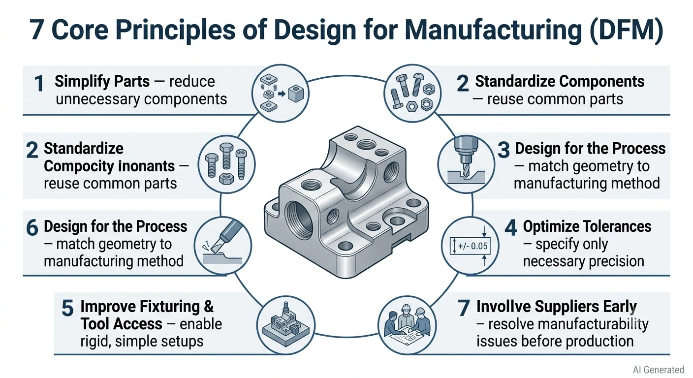
Illustration showing 7 core DFM principles
Every DFM principle below comes with a quantified claim because design for manufacturability
without numbers is just design opinion. These are the principles that DFM in engineering actually uses.
1. Simplify: Minimize Part Count
The Boothroyd Dewhurst three-question test asks of each part: Does it move relative to all other parts already assembled? Must it be a different material from adjacent parts? Must it be separate for assembly or service access? If the answer to all three is no, the part is a consolidation candidate.
(Boothroyd & Dewhurst, Product Design for Manufacture and Assembly, CRC Press 2010)
The strongest DFM work goes beyond confirming that a part is manufacturable, it exposes the cost drivers behind a design so engineers can change geometry, materials, tolerances, and process assumptions early, when the cost of iteration is low. Part count reduction is where the biggest DFM savings typically live. A 30% reduction in part count lowers assembly time by approximately 42% and reduces associated fastener, tolerance stack-up, and quality inspection costs proportionally. DFM parts analysis starts here.
2. Standardize Components
Using the same fastener type across a product family reduces SKU count in most assembly-intensive products. Standardization in DFM manufacturing applies to fasteners, materials, hole sizes, and finish specifications. When a production line carries ten different screw types instead of two, the inventory, kitting, and error-proofing costs accumulate at every unit.
Standardized components also reduce supplier count, simplify qualification, and allow volume pricing that reduces piece-part cost for common commodity items. Fewer unique components can also reduce assembly errors and improve quality.
3. Design for the Process
This is where DFM in engineering gets process-specific. A geometry that's trivial to injection mold may be expensive to CNC machine, and vice versa.
The following DFM principles are based on JLC3DP’s manufacturing capabilities and general engineering recommendations.
| Process | Key DFM Rule | Geometry Constraint |
|---|---|---|
| Injection molding | Uniform wall thickness, draft angles, and proper parting design | Avoid sharp internal corners and undercuts unless side actions are used |
| CNC machining | Ensure tool accessibility and minimize machining setups | Avoid deep narrow features; consider tool diameter and internal corner radius |
| Sheet metal | Maintain proper bend radius and feature placement | Avoid holes and features too close to bend lines or edges |
| FDM 3D Printing | Optimize build orientation and minimize support structures | Minimum wall thickness: 1.2 mm; overhangs typically above 45–60° may require supports |
| SLA 3D Printing | Optimize support placement, surface orientation, and resin drainage | Minimum wall thickness: 0.8 mm; hollow parts require escape holes for resin removal |
| SLS 3D Printing | Design self-supporting geometries and consider powder removal | Minimum wall thickness: 1.0 mm; no external supports required; enclosed cavities require escape holes |
| MJF 3D Printing | Optimize part orientation, packing efficiency, and consistent wall thickness | Minimum wall thickness: 1.0 mm; avoid large uneven sections that may cause deformation |
| SLM Metal 3D Printing | Reduce support volume, control thermal stress, and consider post-machining | Minimum wall thickness: 1.5 mm; supports required for certain overhangs |
| Binder Jetting (BJ) | Consider sintering shrinkage and dimensional compensation | Minimum wall thickness: 1.5 mm; design should account for post-sintering dimensional changes |
4. Loosen Tolerances Where Possible
This is the DFM principle that produces the most dramatic cost savings per decision and the one engineers most consistently ignore. Every step tighter in tolerance multiplies cost:
| Tolerance Range | Relative Cost Multiplier | Typical Process |
|---|---|---|
| ±0.5mm | 1× (baseline) | Standard CNC milling |
| ±0.1mm | 1.5-2× | Finish pass, careful setup |
| ±0.05mm | 2-3× | Precision CNC, in-process gauging |
| ±0.025mm | 3-5× | Precision grinding or fine boring |
| ±0.010mm | 5-10× | Precision grinding + temperature control |
| ±0.005mm | 10-20× | Lapping, dedicated precision equipment |
The DFM approach here is straightforward: specify the loosest tolerance that the function permits. A tolerance that's tighter than necessary doesn't improve the product, it inflates the manufacturing cost for no functional gain.
5. Design for Ease of Fixturing and Tooling Access
Parts that can't be held rigidly during machining add setup time and produce inconsistent results. DFM process guidelines for fixturing: include flat, parallel clamping surfaces; avoid geometries that require custom fixturing; keep features accessible from the minimum number of setups. An additional CNC setup adds the machine time regardless of how fast the actual cutting is. At $80-150/hour machine rates, three extra setups add $48-$135 per part before material is considered.
Undercuts in injection molding require side actions that add $2,000-15,000 to tooling cost and complicate mold maintenance throughout the tool's life. DFM mechanical engineering catches these in design, not after tooling is built.
6. Minimize Secondary Operations
Every secondary operation, deburring, heat treatment, anodizing, painting, pressing in inserts, is a separate handling event with its own setup, labor, and quality check. A typical cost breakdown for a mid-complexity machined aluminum part:
| Operation Stage | Cost Contribution |
|---|---|
| Primary machining | 45-55% |
| Deburring and cleaning | 8-12% |
| Anodizing (outsourced) | 15-25% |
| Inspection | 10-15% |
| Packaging/handling | 5-8% |
DFM design for manufacturing targets the secondary operation cost by designing features that self-deburr (chamfers at edges), selecting materials that don't require surface treatment for the application, and combining finishing operations where possible.
7. Enable Early Supplier Involvement
Suppliers see different problems than designers. A supplier who's been producing similar parts knows that a specific geometry will warp during heat treatment, or that a surface finish specification will require an extra step the drawing didn't account for. Early supplier involvement in the DFM process reduces design iterations by 30-50% in programs that implement it systematically (McKinsey & Company, Product Development Benchmarking studies).
DFM approach in practice: share early CAD files, not just final drawings. Engineering DFM works best as a dialogue, not a document.
What Are the 5 Steps of the DFM Process?
The DFM manufacturing process follows a structured sequence that converts design intent into manufacturable geometry before production commitment.
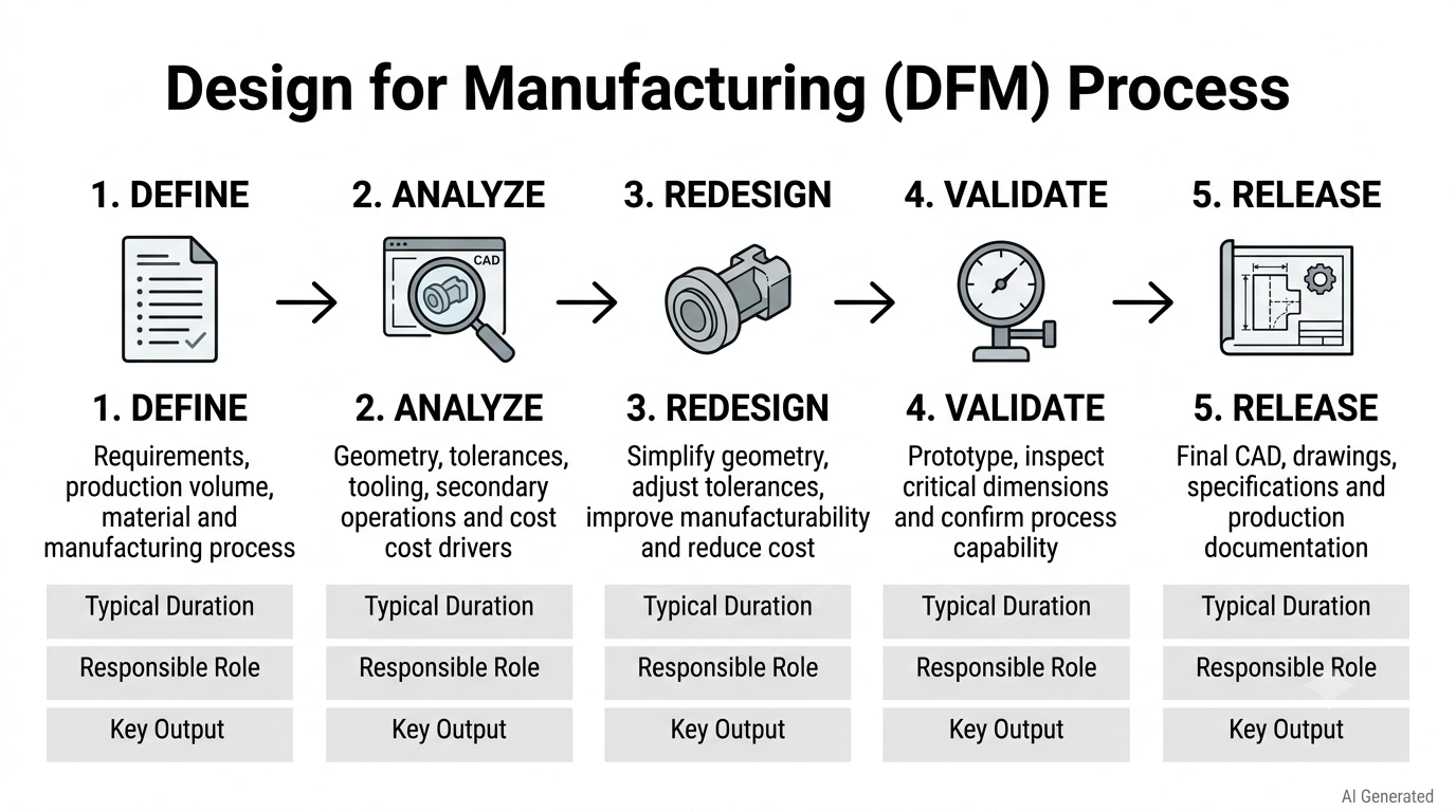
Design for manufacturing process steps
Step 1: Define Requirements and Process Selection Duration
1-3 days for standard consumer products; 1-2 weeks for complex industrial components Responsible: Design Engineer + Manufacturing Engineer Output: Process selection decision, initial design constraints
Define what the part needs to do, at what volume, in what material, and to what quality level. Select the manufacturing process based on volume, geometry, and functional requirements. The design for manufacturing process selection determines every DFM rule that follows, a part designed for injection molding and then switched to CNC machining late in development typically needs a full DFM redesign.
Step 2: Analyze the Current Design for Cost Drivers Duration
Time: 2-5 days (desktop analysis) to 2-3 weeks (formal DFMA software analysis)
Responsible: Manufacturing Engineer + Cost Engineer
Output: DFM analysis report with ranked cost drivers
Apply the 7 DFM principles systematically to the current design. Use the Boothroyd Dewhurst three-question test on every component. Quantify the cost of each tolerance, each secondary operation, each custom component. Rank findings by cost impact to focus redesign effort where it matters most.
Step 3: Redesign for Manufacturability Duration
1-4 weeks depending on scope of changes
Responsible: Design Engineer + Supplier (if involved)
Output: Revised CAD models and drawings with DFM comments resolved
Generate redesign alternatives for the highest-impact cost drivers. This is where DFM in product design is most creative, combining parts, changing material, adjusting geometry to work with the selected process rather than against it. Document why each change was made for future reference.
Step 4: Validate the Redesign Duration
1-2 weeks (prototype testing) to several months (regulatory validation)
Responsible: Design Engineer + Quality Engineer
Output: Validation test report, confirmed tolerance capability
Confirm that redesigned parts meet functional requirements and that the manufacturing process can hold the specified tolerances. For regulated industries (medical, aerospace), this step has defined protocols. For consumer products, functional testing and prototype evaluation are standard.
Step 5: Release for Production with DFM Documentation Duration
1-3 days
Responsible: Design Engineer + Manufacturing Engineer
Output: Released drawings, DFM notes, process specifications
Release the design with complete manufacturing documentation, not just drawings, but DFM notes explaining critical features, tolerance rationale, and process requirements that drawings alone don't communicate. DFM production documentation reduces re-engineering when parts are transferred between suppliers or manufacturing sites.
How Is DFM Applied in Product Design and Mechanical Engineering?
DFM in engineering looks different depending on which role is applying it.
For Design Engineers
DFM in product design means making material and geometry decisions with manufacturing cost in mind from the first sketch. Specifically: select materials that are available in standard stock sizes (reducing raw material cost), model features that are accessible from the planned number of machine setups, and run tolerance stack-up analysis to verify that assembled dimensions meet requirements without over-tightening individual feature tolerances.
The most impactful DFM decision a design engineer makes is usually the material selection, because material determines the process, and the process determines the entire DFM ruleset. Engineering design for manufacturing starts with this decision, not with the detailed feature geometry.
For Mechanical Engineers
DFM mechanical engineering focuses on the interface between structural requirements and manufacturing constraints. Stress analysis informs where tight tolerances and smooth surfaces are functionally necessary (stress concentration points, bearing surfaces, sealing faces) and where they're not (internal non-functional surfaces, stiffening ribs that carry no contact load). DFM mechanical decisions: add material to features that would otherwise need tight tolerances to work, consolidate load paths to reduce part count, specify fixture surfaces that allow rigid workholding.
DFM mechanical engineering also covers assembly sequence optimization, designing the assembly order so that each component can be added without obstructing access to subsequent components, reducing assembly time and error rate.
For Product Managers
DFM in engineering has a clear ROI framework. The cost of implementing DFM, engineering time to analyze and redesign, typically runs 1-3% of total development budget. The savings appear across the product's entire production run: every unit manufactured at lower cost recovers that DFM investment faster at higher volume.
Break-even calculation: if DFM analysis and redesign costs $50,000 in engineering time and reduces per-unit manufacturing cost by $3, the investment pays back at 16,667 units produced. At 100,000 units per year, that's under 2 months of production.
DFM in Production: What Changes at Scale?
A design that works well for a single prototype may not be the most cost-effective solution for production. As manufacturing volume increases, DFM priorities shift from rapid prototyping and low upfront cost toward repeatability, automation, process stability, and long-term cost efficiency.
The DFM approach that's correct for a 100-unit prototype run is often wrong for a 100,000-unit production run, and the reverse is equally true. DFM methodology must account for volume.
1. Prototype Stage: Design for Speed and Flexibility
1–100 units
DFM priorities:
| Factor | Focus |
|---|---|
| Manufacturing speed | Fast iteration |
| Design changes | Easy modification |
| Investment | Avoid tooling cost |
| Production method | 3D printing, CNC machining |
At this stage, additive manufacturing is often preferred because it allows engineers to validate form, fit, and function without investing in expensive tooling.
2. Low-to-Medium Volume Production: Optimize Cost Without Tooling
100–10,000 units
DFM changes:
DFM does not simply ask whether a part can be manufactured. It asks: “How can this part be manufactured efficiently?”.
| Consideration | DFM Focus |
|---|---|
| Material selection | Balance performance and cost |
| Part geometry | Reduce unnecessary complexity |
| Manufacturing process | Choose the most suitable technology |
| Batch production | Improve build efficiency |
3D Printing technologies such as SLS and MJF can remain competitive for low-to-medium volume production because they eliminate tooling costs and support complex geometries that are difficult to manufacture using traditional methods.
For a detailed breakdown of how additive manufacturing costs change with production volume, see our 3D Printing Cost Comparison Guide.
3. High-Volume Production: Optimize for Repeatability and Unit Cost
10,000+ units
At higher production volumes, DFM decisions focus more heavily on automation, cycle time, tooling investment, and process consistency.
| Factor | Impact |
|---|---|
| Tooling investment | Higher upfront cost |
| Cycle time | Lower cost per part |
| Automation | Improved consistency |
| Process control | Reduced variation |
Injection molding often becomes more economical at high volumes because tooling costs are distributed across thousands of parts.
4. Manufacturing Process Selection by Production Volume
| Process | Best Volume Range | Main DFM Consideration |
|---|---|---|
| 3D Printing | 1–10,000+ (depending on technology) | No tooling, design freedom |
| CNC | 1–1,000+ | Machining access and setup reduction |
| Injection molding | 5,000+ | Tooling cost and cycle time |
5. Tooling Investment and Cost Trade-offs
Injection molding often requires significant upfront tooling investment. Tooling costs may range from $20,000–$80,000, making low-volume production expensive. However, once tooling costs are distributed across thousands of parts, injection molding can become more economical.
For many mid-complexity plastic parts, the crossover point between injection molding and CNC machining is often around 2,000–8,000 units, depending on part size, complexity, material, and tooling requirements.
6.Example: Why Prototype Design Is Not Always Production-Ready
A published Fictiv case study demonstrates how redesigning parts for production can reduce tooling and manufacturing costs.
Purcell redesigned its parts for injection molding with Fictiv's DFM and manufacturing guidance, resulting in 38% lower upfront tooling costs, 15% lower ongoing manufacturing costs, and 30–40% lower landed costs. Lead times fell by 40%, while product margins increased by 20%. The takeaway is simple: a design optimized for prototypes isn't necessarily economical at production volume. DFM helps identify those cost drivers before tooling and production are committed.
DFM for 3D Printing: What Traditional Rules No Longer Apply
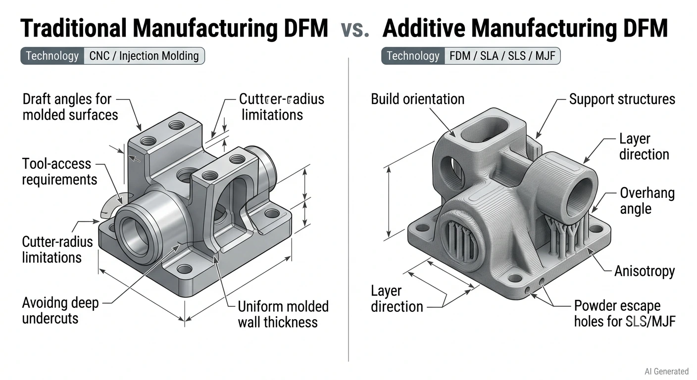
Traditional manufacturing DFM vs additive manufacturing DFM
Additive manufacturing breaks many of the DFM in manufacturing rules that decades of subtractive and molding experience established. Engineers applying traditional DFM design for manufacturing principles to 3D printing designs either over-constrain the geometry unnecessarily or miss the real DFM challenges that additive manufacturing introduces.
Traditional DFM Rules That Become Irrelevant
| Traditional DFM Rule | Why It Doesn't Apply in 3D Printing |
|---|---|
| Draft angles 1-3° on molded surfaces | No mold, parts build and remove vertically |
| Uniform wall thickness (injection molding) | Additive manufacturing does not require the uniform wall thickness rules used in injection molding, but significant wall-thickness variations can still affect printability, cooling, shrinkage, strength, or post-processing depending on the technology. |
| Avoid undercuts | SLS/MJF: no undercuts because no molds; FDM: undercuts achievable with supports |
| Minimum part radius matches tool radius | No cutter radius, geometry is built, not cut |
New DFM Considerations Unique to Additive Manufacturing
Support structures in FDM add material cost and post-processing time. DfAM (design for additive manufacturing) minimizes supports by designing overhangs at 45° or less and orienting the part to put critical surfaces away from support contact.
Build orientation determines surface finish quality, layer line direction relative to load direction, and support structure requirements simultaneously.
Layer adhesion anisotropy is a property that doesn't exist in injection molding or casting. FDM parts are weaker between layers than within layers. DFM principles for additive manufacturing design critical features so primary loads run in the X-Y plane, not through the Z (build) axis.
3D Printing DFM Design Guidelines by Technology
| Factor | FDM | SLA | SLS | MJF | SLM | Binder Jetting (BJ) |
|---|---|---|---|---|---|---|
| Min wall thickness | 1.2 mm | 0.8 mm | 1.0 mm | 1.0 mm | 1.5 mm | 1.5 mm |
| Supports required | Required for overhangs (typically >45–60°) | Required for certain geometries and overhangs | No external supports required | No external supports required | Required; supports help reduce deformation and manage thermal stress | No printing supports required; powder bed provides support |
| Anisotropy concern | High | Moderate | Low | Low | Moderate | Low to Moderate |
| Typical tolerances | ±0.3 mm (≤100 mm); ±0.4% (>100 mm) | ±0.2 mm (≤100 mm); ±0.3% (>100 mm) | ±0.3 mm (≤100 mm); ±0.4% (>100 mm) | ±0.3 mm (≤100 mm); ±0.4% (>100 mm) | ±0.3 mm (≤100 mm); ±0.4% (>100 mm) | ±0.3 mm or ±0.4% (depending on part size and sintering conditions) |
| DFM priority | Orientation optimization + support minimization | Surface orientation + support placement + hollow structure design | Powder escape holes + uniform wall thickness + thermal management | Build orientation + packing density optimization for cost efficiency | Support reduction + thermal stress control + machining allowance | Shrinkage compensation + sintering deformation control + powder removal |
Note: The values above are JLC3DP’s general DFM recommendations. Actual printability may vary depending on material selection, part geometry, build orientation, and post-processing requirements. For detailed design rules by technology, see JLC3DP’s 3D Printing Design Guideline.
How JLC3DP Applies DFM Principles to Real Manufacturing
Upload CAD Files and Review Manufacturability
Upload STEP, STL, OBJ, or 3MF files to JLC3DP's platform for automated geometry compatibility checking. The system identifies potential manufacturing issues, wall thickness violations, unsupported features, geometry that falls outside achievable tolerances for the selected process, before production commitment. An instant quotation returns with the file review, so design and cost are visible simultaneously.
Receive DFM Feedback Before Production
JLC3DP's engineering review flags the specific issues that cause production problems: walls below process minimums, unsupported features that require redesign or process change, geometrically complex sections that drive cost disproportionately, tolerance specifications that require secondary operations not accounted for in the design, and surface finish requirements that need clarification. This DFM feedback arrives before production starts, when it's cheap to act on.
Select the Right Material and Manufacturing Process
Material and process selection at JLC3DP covers the full spectrum from standard PLA and nylon for early-concept prototypes through engineering-grade PEEK and titanium for end-use components. DFM approach on material selection: the engineering team advises where material substitution reduces cost without compromising function, and where the initially specified material is the correct choice and why.
From Prototype Validation to Production Manufacturing
The DFM production pathway at JLC3DP runs from prototype testing (single units, design validation) through design iteration (revised files, updated quotes) to low-volume production (10-500 units, production-intent quality) and end-use parts (certified materials, inspection documentation). Using one supplier through this progression maintains DFM consistency, the supplier who provided feedback on the prototype design is the one producing the production parts.
Explore JLC3DP's 3D printing service for DFM-supported manufacturing from prototype to production.
What JLC3DP's DFM Review Checks
| Check | What We Review |
|---|---|
| Wall thickness | Minimum wall thickness by process |
| Feature size | Smallest printable/manufacturable features |
| Tolerances | Process capability vs specified tolerance |
| Overhangs | Support requirements |
| Hollow parts | Drainage / powder removal |
| Orientation | Surface quality and mechanical performance |
| Material | Material-process compatibility |
| Post-processing | Machining / finishing allowance |
FAQ About Design for Manufacturing (DFM)
Q: What is the difference between DFM and DFA?
DFM (design for manufacturing) focuses on reducing piece-part cost by designing parts that are easier to machine, mold, or print. DFA (design for assembly) focuses on reducing assembly time and error rate by minimizing part count and simplifying how parts go together. DFMA combines both. Most products benefit from applying both, DFM reduces what each part costs, DFA reduces how many parts there are.
Q: How much does DFM reduce manufacturing costs?
80% of manufacturing cost is locked in during design. DFM redesigns typically reduce piece-part cost 15-30% for individual components. Full DFMA product redesigns, combining part count reduction with process optimization, achieve 50-80% total cost reduction in documented Boothroyd Dewhurst case studies across automotive, consumer electronics, and industrial equipment. The earlier DFM is applied, the larger the achievable savings.
Q: When should DFM analysis be performed in the product development cycle?
DFM in design should begin at concept stage, before geometry is detailed, before materials are committed, and before any tooling is considered. DFM considers process selection, material, geometry, tolerances, tooling, production volume, and quality requirements before a design is released, while changes are still cheap to make. A DFM analysis after tooling is committed finds the same problems but can no longer fix them without cost.
Q: What software tools support DFM analysis?
Boothroyd Dewhurst DFMA software is the industry standard for quantitative DFM and DFA analysis, covering 25+ manufacturing processes with should-cost modeling across 22 countries. Supplementary tools include Siemens NX (integrated DFM checking in CAD), CATIA with manufacturing simulation modules, and manufacturing platform DFM checkers from JLC3DP, Protolabs, and Xometry that flag obvious geometry issues automatically at quote stage.
Q: Can DFM be applied to low-volume or custom manufacturing?
Yes, DFM in engineering is more valuable at low volume, not less. High-volume production amortizes tooling and setup cost across many parts; low-volume production carries that full cost per unit. Every DFM improvement at low volume shows up directly in per-unit cost. Custom parts for one-off or small-batch applications benefit particularly from DFM methodology because there's no production run over which to recover poor design decisions.
Keep Learning
15 Tips for Fast 3D Printing
3D printing can be time-consuming, but there are some strategies to speed up the process without sacrificing too much quality. Below are 15 practical tips to speed up your 3D printing process while maintaining decent quality. These tips are especially useful for prototyping or when speed is a priority: 1. Increase Layer Height ● Why: Thicker layers mean fewer layers overall, reducing print time. ● How: Adjust the layer height in your slicer settings. For example, go from 0.2mm to 0.3mm or higher. ● Tr......
How to prevent 3d printing warping problems
3d printing warping is one of the most common problems faced by 3d printing enthusiasts. Especially when printing larger models, the printed parts initially adhere to the print bed, but then the edges of the prints lift off the print bed and curl, causing the model to deform and waste material. The main reason for warping is that plastic materials cool and shrink when printed, which causes deformation. This article will analyze the causes of warping and use suggestions to prevent 3d printing warping t......
How to 3D Print Wood
3D printing has revolutionized the manufacturing industry by allowing the creation of complex and customized objects. While 3D printing with plastic and metal has been widely adopted, the ability to 3D print with wood has opened up new possibilities for creating aesthetically pleasing and environmentally friendly products. In this article, we will explore the process of 3D printing with wood and the techniques involved in achieving the desired results. Understanding Wood Filament The key to 3D printin......
Design for Manufacturing (DFM): 7 Principles, Process & Practical Guide
Key Takeaways Design for Manufacturing (DFM) is a design strategy that connects product requirements with manufacturing capabilities. A successful DFM approach requires choosing the right process, simplifying designs, reducing unnecessary complexity, and considering production volume from the beginning. Different manufacturing methods have unique design considerations. By applying DFM principles early, engineers can reduce redesign risks, improve product quality, shorten production cycles, and create ......
3MF VS STL: Which File Format Is Better for 3D Printing?
In the additive manufacturing industry, the STL format has served as the de facto standard for decades. However, the rapid evolution of modern 3D printing has highlighted its technical limitations. Consequently, the 3MF format—backed by an industry consortium including Microsoft, HP, and Ultimaker—has emerged as a robust, next-generation alternative. When exporting a 3D model from CAD or preparing it within a slicer, understanding the technical nuances of 3MF VS STL is critical. This article provides ......
Design for Additive Manufacturing: A Practical DfAM Guide
Key Takeaways DfAM is not DFM: Design for additive manufacturing focuses on exploiting AM's geometric freedom rather than simply simplifying parts. Build orientation matters: Orientation affects strength, surface finish, supports, thermal distortion, and overall cost. Design for the process: Wall thickness, overhangs, holes, clearances, and tolerances must match the specific AM technology and material. Complexity can reduce cost: Part consolidation, lattices, and internal channels can deliver value th......