What Is B-rep (Boundary Representation) in CAD?
13 min
- What Is B-rep (Boundary Representation)?
- How B-rep Works: Faces, Edges, and Vertices
- Why B-rep Matters in CAD Modeling
- B-rep vs Mesh: Key Differences
- Common CAD File Formats That Use B-rep
- FAQ about B-rep (Boundary Representation) in CAD
- Conclusion: B-rep (Boundary Representation) in CAD
Key Takeaways
B-rep (boundary representation) is the method CAD systems use to describe a 3D object by its boundaries: the faces, edges, and vertices that enclose it. It pairs topology, how those elements connect with exact mathematical surfaces, which is why B-rep models support precise measurement and manufacturing.
B-rep combines two layers. Topology records face-edge-vertex connectivity; geometry stores the mathematical equations (planes, cylinders, NURBS) those elements sit on. Mesh formats carry only discrete vertices and facets.
It is the core architecture of mainstream CAD kernels, including Parasolid and ACIS, and it underpins both solid modeling and surface modeling.
“Watertight” belongs to solid bodies, not to B-rep itself. A solid body’s boundary is closed; a sheet or surface body is legitimately open, and still B-rep.
Exact surfaces mean exact properties. Volume, mass, and centre of gravity can be computed from the equations rather than estimated from triangles.
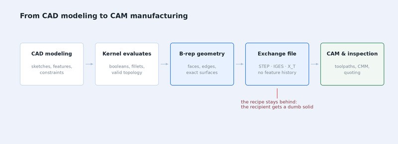
Exchange formats carry the B-rep but not the recipe. STEP, IGES, and X_T hand over finished geometry without the feature history, which is why an imported STEP or X_T part usually arrives as a “dumb solid” (and IGES often as surfaces).
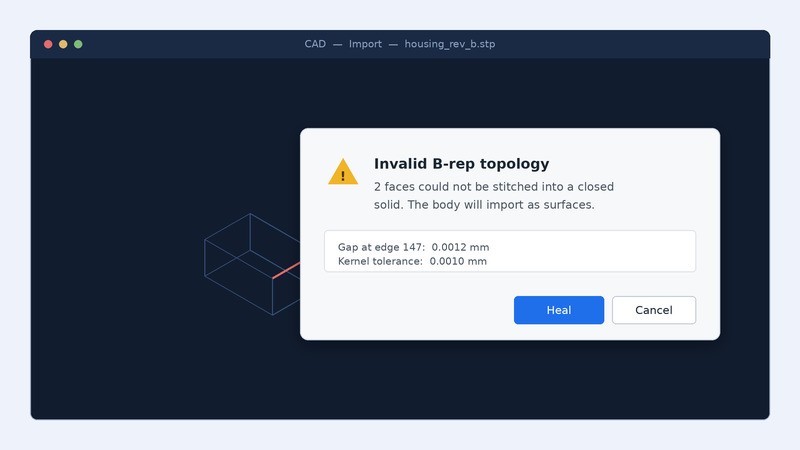
You export a part to STEP for a supplier, they open it in a different CAD system, and something in the exchange goes wrong: a warning about invalid topology, a body that imports as surfaces instead of a solid, a healing prompt you have never seen before. Somewhere in that message is the term B-rep, and the software assumes you already know what it means.
This guide explains what B-rep (boundary representation) is, how its data structure works, why it matters in CAD modeling and manufacturing, and which file formats are built on it. If you work with STEP, IGES, or X_T files, you can also open and inspect them directly in a browser with the JLCDMP 3D Viewer, which reads these B-rep formats without a CAD installation.
The scope here is fundamentals and their practical consequences in CAD and manufacturing, not a modeling tutorial.
What Is B-rep (Boundary Representation)?
B-rep, short for boundary representation, describes a three-dimensional object by defining its boundary: the faces, edges, and vertices that separate what is inside the object from what is outside. The shape is never stored as a filled volume. It is stored as the skin around the volume, described precisely enough that the software can reason about the space the skin encloses.
Two kinds of information make that possible, and keeping them distinct is the key to understanding every B-rep behaviour that follows.
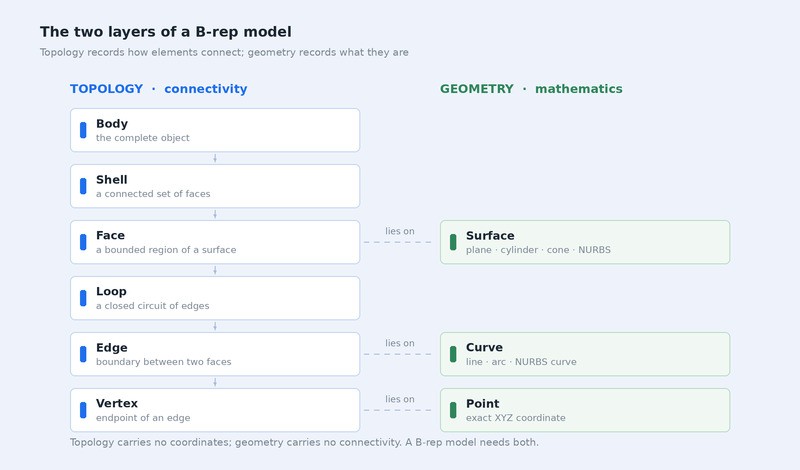
Topology is connectivity. It records which edges bound which face, which vertices sit at the ends of which edge, and which faces are adjacent to which. It carries no coordinates at all, only relationships.
Geometry is the mathematics. Each face points to an underlying surface equation: a plane, a cylinder, a cone, a torus, or a NURBS surface for anything freeform. Each edge points to a curve, and each vertex to a point in XYZ space.
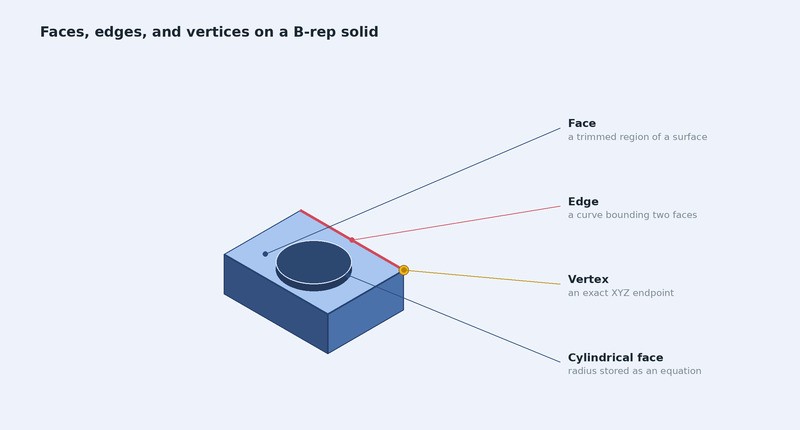
A cylindrical hole illustrates the split neatly. The geometry says “cylindrical surface, radius 6.000 mm, axis along Z.” The topology says “this face is bounded by two circular edges, and it is adjacent to the top and bottom faces of the plate.” Change the radius and the geometry updates while the topology stays identical. That separation is what lets CAD systems modify shapes without rebuilding the entire description.
There is a practical wrinkle worth knowing about. Kernels do not insist on perfect mathematics; they work to tolerances, and each kernel and translator uses its own tolerance. Two faces whose edges differ by less than that tolerance are treated as joined, which is what makes filleting and booleans robust in the real world. It also means “exact” describes the surface equations rather than the stitching between them, and that distinction is behind most translation trouble.
One widespread claim needs correcting here. B-rep models are often described as watertight, but watertight is a property of solid bodies, not of B-rep as such. A solid body has a closed, fully connected boundary with no gaps. A sheet body, a single surface, a trimmed patch, an open shell, is also B-rep, and it is open by design. Surface modeling and solid modeling both run on the same underlying representation.
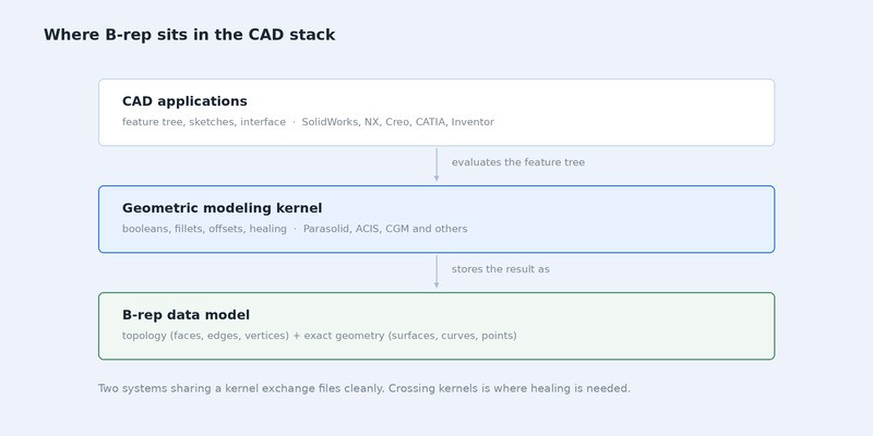
B-rep is the data architecture of the major geometric modeling kernels, Parasolid and ACIS among them. A kernel is the engine underneath the interface: it performs the booleans, filleting, and offsetting that turn user operations into valid geometry. When two CAD systems share a kernel, files move between them usually more cleanly. When they do not, translation is where problems appear.
How B-rep Works: Faces, Edges, and Vertices
A B-rep model is organised as a hierarchy, and the order matters more than most summaries admit.
At the top sits the body, the complete object. Below it are shells, each a connected set of faces, a solid with an internal cavity has two, one for the outer skin and one for the void. Below shells come faces, each a bounded region of an underlying surface. Each face is enclosed by one or more loops of edges, and each edge terminates at vertices.
So a face is a fundamental element, but it is not the top of the structure. Faces are contained within shells and bodies, not the other way around. Getting this right explains why a CAD system can report “two bodies” when you expected one, or why deleting a face can leave a valid open sheet rather than an error.
The three elements people meet in practice:
- Face - a trimmed piece of a surface. The underlying surface may be infinite, as a plane technically is; the loops of edges cut out the finite patch the part actually uses.
- Edge - in a closed solid, the boundary between exactly two faces, carrying its own curve equation: a line, a circular arc, or a NURBS curve for freeform transitions.
- Vertex - the endpoint where edges meet, stored as an exact XYZ coordinate.
Topology binds these into a coherent whole by recording adjacency. Because the model knows that face A and face B share edge E, it can determine that the boundary is closed, calculate the enclosed volume, and offset the whole thing by 2 mm without losing track of which neighbour belongs to which.
This is also where imports fail. If a translated edge leaves a gap of 0.01 mm between two faces, the geometry still looks correct on screen, but the topology no longer closes, and the receiving kernel reports a shell that cannot become a solid. The geometry was fine; the connectivity was not.
Why B-rep Matters in CAD Modeling
Precision. Because surfaces are stored as equations, a radius is exactly the radius specified, at every point, at any zoom level. There is no resolution setting and no deviation to tune. What you see on screen, in CAD or in a web viewer, is a tessellated display mesh; the stored surfaces stay exact.
Engineering analysis. Volume, mass, centre of gravity, and moments of inertia come from integrating over exact surfaces, so the numbers are accurate rather than approximated. FEA meshers also work far better from clean B-rep input, because they can refine the mesh against the true surface instead of against a fixed set of triangles.
Parametric editing happens one level up. This is the point that causes the most confusion. Your feature tree, extrude, fillet, pattern, lives in the CAD application. The kernel evaluates that tree and outputs the resulting B-rep. When you export to STEP, IGES, or X_T, the output travels and the recipe stays behind. The recipient gets accurate geometry with no editable dimensions, which is exactly what “dumb solid” means. Native formats such as SLDPRT or CATPart keep the feature history alongside the geometry, which is why they preserve editability and exchange formats do not.
Feature recognition. CAM and DFM tools read topology to identify machinable features, a cylindrical face with two circular edges reads as a hole, a set of parallel faces reads as a pocket. That inference is only possible because the connectivity is there to be queried, which is why CNC and sheet-metal quoting works best from STEP files, while 3D printing quotes also accept mesh files such as STL.
Manufacturability. CAM systems consume B-rep directly. Toolpath generation needs to know a pocket floor is planar and a boss is cylindrical, not that both are collections of triangles. Mold design, sheet metal unfolding, and CMM inspection routines all depend on the same exactness. When a model crosses kernels, Parasolid to ACIS, say small tolerance differences can leave gaps that need healing before any toolpath will generate.
B-rep vs Mesh: Key Differences
Both describe a 3D shape; they answer different questions. A mesh asks what the surface looks like. B-rep asks what the surface is.
| Dimension | B-rep | Mesh |
|---|---|---|
| Mathematical definition | Exact surfaces and curves with topological connectivity | Discrete vertices joined into flat triangular facets |
| Data precision | Exact; independent of zoom or scale | Approximate; set by chord tolerance at export |
| File size at equal precision | Compact for curved geometry, one equation per surface | Grows quickly; fine curves need many triangles |
| Editability | Parametric editing in native formats; exchange formats arrive as dumb solids | No parametric structure; edits are sculpting or remeshing |
| Engineering analysis | Exact mass properties; preferred input for FEA meshing | Approximate properties; adequate for visualisation |
| Manufacturability | Direct input for CNC, molds, sheet metal, inspection | Suited to 3D printing slicers |
| Typical formats | STEP, IGES, X_T, SAT, SLDPRT | STL format, OBJ, 3MF, GLB |
When to choose which. If your downstream work involves CNC programming, FEA, parametric iteration, or precise volume and mass figures, you need B-rep data. If the goal is visualisation, web viewing, 3D printing slicing, or real-time rendering, a mesh is sufficient and considerably faster to load. Plenty of workflows use both: B-rep for design and analysis, mesh for sharing and display.
The file size row deserves a concrete example. A turned shaft with a few diameters and a fillet might be a few hundred kilobytes as STEP, because each surface is one equation and a handful of parameters. Exported as a mesh fine enough to machine from, the same part can run to tens of megabytes, and it still will not be exact. For flat-faced parts the comparison narrows, and for heavily faceted scan data the mesh can be the smaller file.
Common CAD File Formats That Use B-rep
B-rep is the underlying architecture of most formats that move engineering data between systems. They differ in how completely they carry the topology. For mesh and print formats, see our guide to 3D printing file formats.
| Category | Format | Extension | Key Characteristics | Typical Use |
|---|---|---|---|---|
| Exchange | STEP | .step, .stp | Can carry full B-rep solids with topology; may also contain open shells or surfaces, depending on the export | Supplier exchange, archiving, manufacturing |
| Exchange | IGES | .iges, .igs | Primarily surfaces and curves; may lack solid topology, so not every IGES file holds a valid solid | Legacy data, surface transfer |
| Kernel | Parasolid | .x_t, .x_b | Native kernel format; high-fidelity transfer between Parasolid-based systems | CAD-to-CAD, CAM input |
| Kernel | ACIS | .sat | Native kernel format for ACIS-based applications | CAD-to-CAD, legacy translation |
| Native CAD | SolidWorks | .sldprt | Stores complete feature history, parametric constraints, and B-rep geometry; the B-rep is the kernel’s evaluated output, not the file’s only content | Active design work |
| Native CAD | CATIA, Creo, NX | .CATPart, .prt | Same structure: history plus constraints plus evaluated B-rep | Active design work |
If you need to open any of these without the originating software, the JLCDMP 3D Viewer handles most of them in a browser, including measuring distances, angles, radii, surface area and volume. Check its homepage for the current list of supported file types.
FAQ about B-rep (Boundary Representation) in CAD
Q: Is NURBS the Same Thing as B-rep?
No, NURBS is one kind of surface geometry, while B-rep is the structure that organises surfaces into a complete object. A B-rep model uses NURBS for freeform faces, but planes, cylinders, and cones are stored as their own analytic types because they are simpler and more robust. Saying a model is “NURBS-based” describes its geometry layer, not its architecture.
Q: Can I Convert a Mesh Back Into B-rep Geometry?
Not reliably, and this is the asymmetry that catches people out. Converting B-rep to mesh is a one-way calculation; going back requires inferring what the original surfaces were. Basic converters turn every mesh facet into its own flat face, giving a heavy faceted solid that is technically B-rep but has no usable features. Some tools can merge facets into planes and cylinders on simple prismatic parts; organic shapes still need manual surface refitting in reverse-engineering software.
Q: How can I open a STEP or X_T file without CAD software?
Use a browser-based viewer. The JLCDMP 3D Viewer opens STEP, IGES, X_T, SAT and SLDPRT files without installation, so you can rotate the part, check its structure tree and measure distances, angles and radii. For editing, you still need CAD software that can import the format.
Q: Does B-rep Handle Organic Shapes Well?
Yes, through NURBS faces, though it is not always the easiest route. Consumer product surfacing, automotive bodywork, and turbine blades are all modelled as B-rep. Highly irregular forms, scanned anatomy, generative lattices, topology-optimised structures, are often more practical as meshes, then converted or rebuilt as B-rep only if they need machining.
Q: Which Format Should I Send to a Manufacturing Supplier?
STEP, in almost every case. It can carry complete solid topology, virtually every CAD and CAM system reads it, and it is the format most job shops expect. Send X_T only if you know the supplier runs a Parasolid-based system and wants maximum fidelity. Send STL only for 3D printing, and pair any format with a drawing when tolerances matter.
Conclusion: B-rep (Boundary Representation) in CAD
B-rep is a foundational data architecture rather than a feature you switch on. It underpins the exchange formats engineers use daily, STEP and IGES among them, and it is the shared basis of mainstream kernels including Parasolid and ACIS. Knowing how it separates topology from geometry explains most of what distinguishes these formats from one another.
It also explains the everyday frictions: why an imported model has no feature tree, why a translated part sometimes needs healing, why a mesh cannot simply be turned back into a solid. None of those are faults in the software. They follow directly from what each representation was designed to do.
Whether you are working in STEP, IGES, or a native CAD format, B-rep is the architecture running quietly underneath, keeping your model precise, manufacturable, and ready for analysis.
Keep Learning
Non-Manifold Edges in 3D Printing and Why Prints Fail
Key Takeaways Non-manifold edges are mesh edges shared by one face or by three or more faces; in a closed printable solid, every edge should join exactly two. Broken or branching layer outlines can leave a slicer unable to determine where solid material belongs. Boolean seams, overlapping bodies, deleted faces and poorly joined exports are common places to find trouble. A viewer reveals visible symptoms; mesh analysis checks connectivity, and the sliced preview checks the proposed print. Spot Mesh Err......
What Is B-rep (Boundary Representation) in CAD?
Key Takeaways B-rep (boundary representation) is the method CAD systems use to describe a 3D object by its boundaries: the faces, edges, and vertices that enclose it. It pairs topology, how those elements connect with exact mathematical surfaces, which is why B-rep models support precise measurement and manufacturing. B-rep combines two layers. Topology records face-edge-vertex connectivity; geometry stores the mathematical equations (planes, cylinders, NURBS) those elements sit on. Mesh formats carry......