Non-Manifold Edges in 3D Printing and Why Prints Fail
14 min
- What Are Non-Manifold Edges in 3D Printing?
- Types of Non-Manifold Geometry
- What Causes Non-Manifold Edges
- Why Non-Manifold Edges Break Your 3D Print
- How to Spot Non-Manifold Problems Before You Slice
- What to Do When You Find Them
- Check Your Model Again After Fixing
- FAQ about Non-Manifold Edges in 3D Printing
- Conclusion: Non-Manifold Edges in 3D Printing
Key Takeaways
Non-manifold edges are mesh edges shared by one face or by three or more faces; in a closed printable solid, every edge should join exactly two.
Broken or branching layer outlines can leave a slicer unable to determine where solid material belongs.
Boolean seams, overlapping bodies, deleted faces and poorly joined exports are common places to find trouble.
A viewer reveals visible symptoms; mesh analysis checks connectivity, and the sliced preview checks the proposed print.
A wall disappears in the sliced preview, yet the model looked complete in your modelling software. Sometimes a non-manifold warning explains the mismatch; sometimes the only clue is strange infill. Non-manifold edges in 3D printing can make a surface ambiguous even when its shaded appearance seems convincing.
This guide explains the geometry, the slicing mechanism and the checks worth making before printing. For broader mesh errors and corrective tools, see our guide to repairing STL files.
You can start without installing anything: a free browser-based 3D viewer helps reveal visible holes and fragments, although it cannot certify that a mesh is manifold.
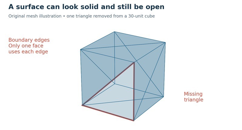
Figure 1. A cube with one triangular face removed; the three resulting boundary edges are marked in red.
What Are Non-Manifold Edges in 3D Printing?
Non-manifold edges in 3D printing are edges that fail the two-face rule used to check a closed solid mesh: each edge should join exactly two faces. An edge with one face marks an opening; an edge with three or more creates a junction that is not an ordinary surface.
Blender's non-manifold selection options also cover edges without faces, boundary edges and inconsistent face orientation. These checks identify different issues, so the warning category matters as much as the count.
Non-Manifold Geometry Explained
Non-manifold geometry includes troublesome vertices as well as edges. Two otherwise closed bodies joined at only one vertex create a point connection with no material thickness. Counting faces around edges alone can miss that condition.
Non-Manifold vs. Watertight
A mesh can have no visible holes and still fail a manifold check. Consider two closed cubes joined along a single shared edge: four faces meet there, although neither cube has an open surface. If “watertight” means only “no boundary holes”, that example passes the description but remains non-manifold. Some tools use a stricter definition of watertight.
Open surfaces can be mathematically manifold surfaces with boundaries. Printing tools often flag those boundaries because the intended output is a closed solid. Consistent face orientation is another requirement: adjacent faces must agree about which side faces outward. Merely having different normal directions around a corner is normal; inconsistent winding is the problem.
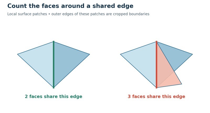
Figure 2. Original topology diagram. Two faces form an ordinary local surface; a third face creates a branch along the same edge.
Types of Non-Manifold Geometry
| Type | What It Is | Possible Print Effect |
|---|---|---|
| Multiple Faces | Three or more faces meet along one edge. | A branching boundary makes the solid region ambiguous. |
| Boundary Edge | Only one face uses an edge. | An open surface can interrupt a layer contour. |
| Wire Edge | An edge has no attached faces. | No printable volume; often omitted during export. |
| Non-Manifold Vertex | Separate surface regions meet at one point. | A zero-thickness joint cannot form a robust connection. |
| Non Contiguous | Two neighbouring faces have inconsistent orientation. | Inside and outside classification may disagree. |
| Internal Faces | Unwanted sheets remain inside the intended solid. | Extra contours can affect walls or fill. |
Blender treats Interior Faces as a separate selection feature. That final row describes a related cause, not an official Non-Manifold selection category. An internal sheet creates a multiple-face edge only where it is connected to the surrounding surface that way. STL stores triangles, so standalone wire edges are not represented as independent edges in an ordinary STL export.
A non-manifold mesh or non-manifold surface may contain several of these defects together.
What Causes Non-Manifold Edges
- Boolean seams. A union or subtraction can leave thin fragments, duplicate surfaces or unjoined boundaries, especially around nearly coincident faces. Inspect the intersection rather than assuming that a completed operation produced a valid solid.
- Overlapping bodies. Joining objects does not necessarily unite their volumes. Shared internal surfaces and intersections may remain; welding touching edges can create branching connections.
- Deleted faces. Removing a triangle opens the surrounding surface. Deleting a face while retaining its edges can also leave loose geometry in the source model.
- Extrusion and vertex merging. An accidental extra extrusion can leave coincident faces. An excessive merge distance can collapse separate features into a point or edge contact. Autodesk documents this risk for vertex merging.
- CAD exports. Unstitched trimmed surfaces or tolerance mismatches can become gaps when tessellated into an STL file. A visually smooth seam may still consist of separate boundaries.
- Scans, sculpting and decimation. Missing scan coverage creates openings; reconstruction and aggressive simplification can damage narrow connections or preserve unwanted fragments.
- AI-generated models. A convincing outer appearance does not establish a printable volume. Inspect thin appendages, overlapping shells and hidden surfaces before trusting the export.
Where the file came from often tells you where to look first.
Why Non-Manifold Edges Break Your 3D Print
From Triangles to Layer Outlines
A slicer intersects a model with horizontal planes at successive heights. Where a plane crosses a triangle, it usually produces a line segment. Those segments must be assembled into boundaries that distinguish material from empty space. CGAL’s documentation describes this geometric stage as intersecting a triangle mesh with a plane.
For a simple closed cube, an ordinary horizontal cut produces a square loop. The slicer can then construct perimeter paths and determine the region available for infill. A hollow part needs additional loops to identify its cavity; those inner loops are intentional, not errors.
Remove a triangle from the cube’s side and some cuts become incomplete. The line ends no longer connect around the whole section. Add a sheet attached to an existing edge and a cut may branch instead. The geometry no longer gives the same straightforward answer about what should be filled.
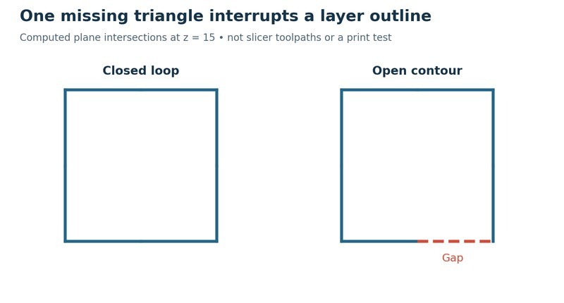
Figure 3. Plane intersections computed from the original cube meshes. The dashed segment is missing from the damaged mesh. This demonstrates an open contour, not an observed slicer outcome.
Why a Wall Can Disappear
If a region cannot be interpreted as a valid solid, the resulting preview may omit it or connect its boundaries differently from the intended design. That can appear as a missing wall, a slot that closes unexpectedly, or an exterior perimeter that changes partway through the model.
However, missing walls are not proof of non-manifold geometry. A perfectly closed feature may be too narrow for the selected process or settings. Check wall thickness alongside mesh connectivity, especially when the same small detail disappears consistently throughout its height.
Why Infill and Surface Gaps Appear
Infill belongs inside a classified region. An unwanted interior sheet or conflicting boundary can affect that classification, creating unexpected partitions, empty regions or fill where a cavity should remain. The effect depends on the geometry and the slicer’s interpretation; an extra face does not always become an extra printed wall.
Top and bottom surfaces also depend on how successive solid regions overlap. If the interpreted cross-section changes around a damaged area, surface coverage may be wrong. A small floating shell can produce an isolated island, while a bare wire or zero-area feature may disappear entirely. Severe ambiguity can prevent slicing from completing.
Why an Import Warning Is Only a Starting Point
Import behaviour varies. A slicer may report a mesh problem, attempt an automatic correction, or proceed with an interpretation that needs checking. Do not treat a disappearing warning as evidence that the intended shape survived. Inspect cavities, mounting holes and thin connections after any automatic processing, and compare them with the source design.
A repair routine cannot know whether an opening is a missing triangle or a feature you intended to keep. Even when it produces a closed result, the result may be geometrically wrong. Make the decision from the layer preview and dimensions, not just from the absence of an error message.
How to Spot Non-Manifold Problems Before You Slice
Some problems leave visible symptoms that you can inspect in a browser. Others remain invisible because coincident vertices or faces occupy exactly the same screen position. Use the visual pass to locate suspicious areas, then investigate connectivity in a mesh tool.
1Open the Model and Establish Its Shape
Open the viewer and upload your STL file. Rotate it before changing display modes. Compare its silhouette, openings and separate components with the intended design, including the underside and surfaces normally hidden by the default view.
2Inspect the Surface in Wireframe
Switch to wireframe and inspect seams, thin junctions and abrupt changes in triangle density. Look for missing patches, unconnected fragments and edges that stop unexpectedly. Rotate again: one viewing angle can hide an opening behind another face.
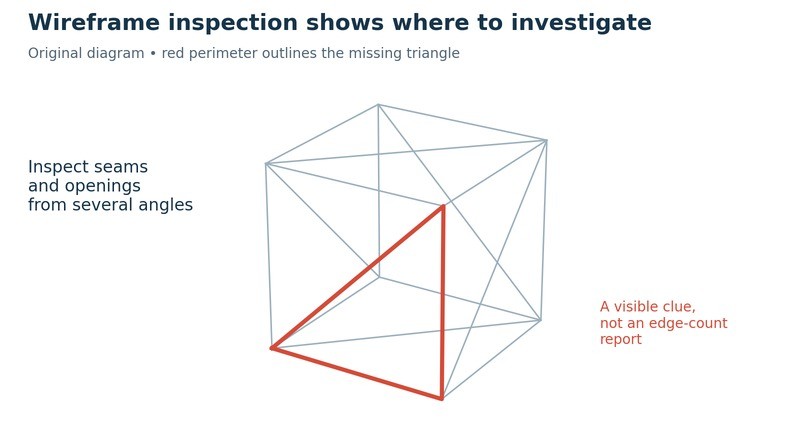
Figure 4.Wireframe view of the test cube showing an open triangular patch where a face is missing.
3Look Inside the Model
Use transparency or sectioning to examine the interior. Move the section through several positions rather than relying on one cut. Look for floating sheets, small disconnected pieces and boundaries that do not match the intended cavity.
Distinguish designed internal structures from leftovers. A rib, separate assembly component or cavity wall may belong there. A section plane also deliberately exposes a cut through the model; that displayed cut is not evidence of a pre-existing hole in the mesh.
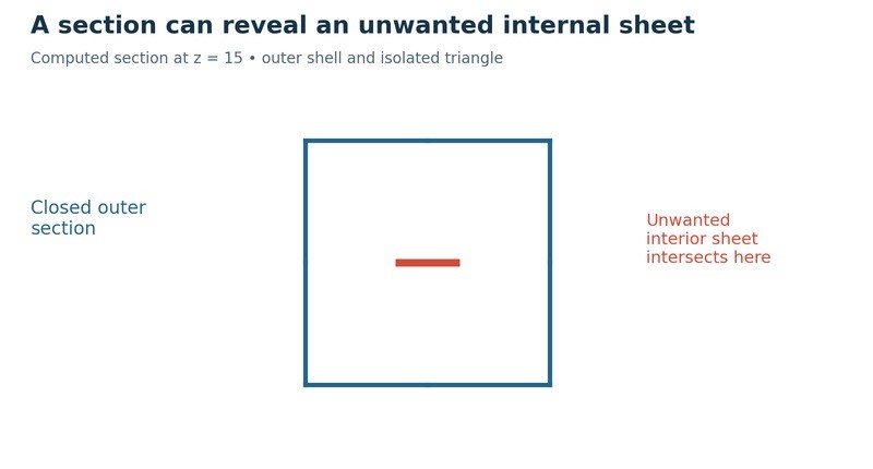
Figure 5. Section through the test mesh showing an isolated internal sheet inside the otherwise closed surface.
4Check Dimensions and Confirm Suspicious Areas
Read the bounding-box dimensions and compare at least one known feature with the design. A sensible-looking shape can still have the wrong scale, and an unexpectedly large bounding box may reveal a distant fragment. Dimension checks complement topology checks; neither replaces the other.
For precise selection, use Blender in Edit Mode with vertex or edge selection active, then Select → Select All by Trait → Non-Manifold. Inspect the selection options and enable edge statistics if you need counts; face-selection mode does not expose this command.
The separately installed 3D Print Toolbox provides additional mesh analysis. The browser viewer is a quick visual starting point, while Blender checks the underlying mesh. Slicer warnings and the final layer preview add another check on how that geometry is interpreted.
What to Do When You Find Them
Match the correction to the defect in your modelling or mesh software. Merge duplicate vertices only where they should connect, remove loose geometry and unintended internal faces, and resolve overlapping solids according to the intended design. Separate bodies that should remain distinct instead of welding every contact together. If repeated repairs damage functional features, return to the source model and rebuild the troublesome area.
| Defect | Typical fix |
|---|---|
| Boundary edges (holes) | fill the hole, then recheck |
| Multiple faces / internal sheets | delete interior faces or boolean-union overlapping bodies |
| Duplicate vertices | Merge by Distance with a small threshold |
| Non contiguous | Recalculate Outside |
| Non-manifold vertex | separate or thicken the joint |
| Whole model | 3D Print Toolbox (install via Edit → Preferences → Get Extensions) → Make Manifold |
Corrections can change shape, close intended openings or erase detail. Recheck the result rather than assuming repair preserved the design. For the detailed procedure, follow the full STL repair workflow.
Check Your Model Again After Fixing
Re-upload the corrected file and repeat the same views. Confirm that unwanted holes and fragments are gone, intended cavities remain, and known dimensions still match. Use a mesh analysis check again as well: an improved appearance is useful evidence, but it is not a topology certificate.
STL does not encode a standard unit setting. A mismatch between inches and millimetres can make the model 25.4 times too large or too small. Check the actual dimensions after import instead of relying on how large the model looks on screen.
If you need another person’s judgement, a viewer share link can help a designer or colleague examine the same geometry. Point them to the affected feature and describe the intended result. Finally, slice the corrected file and check the layers around every repaired region.
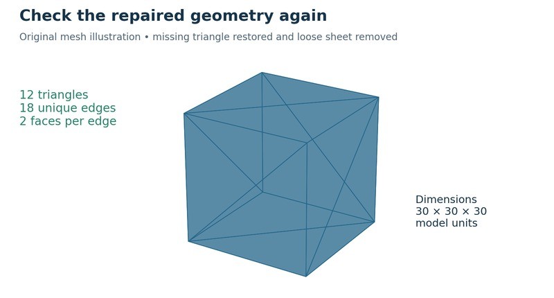
Figure 6. The corrected test mesh: every edge is shared by exactly two faces.
FAQ about Non-Manifold Edges in 3D Printing
Q: Can I Ignore a Warning if the Preview Looks Correct?
A correct-looking preview reduces concern but does not justify ignoring an unexplained warning. Identify the affected geometry and examine the relevant layers closely, including small cavities and connections. For a functional part, compare critical dimensions with the source design. A warning caused by irrelevant leftover geometry may be easy to resolve, while a damaged load-bearing feature deserves further investigation.
Q: Does Increasing Mesh Resolution Remove These Problems?
Increasing mesh resolution does not automatically repair connectivity. Subdividing existing triangles usually adds detail while preserving the original openings or branching junctions. Exporting again from a valid source solid may help when tessellation caused the problem, but simply making an already damaged STL denser can make inspection harder. Correct the underlying defect before choosing the resolution needed for surface quality.
Q: Can a Model with Several Separate Parts Be Valid?
Yes, several separate closed shells can be valid when the design intentionally contains separate parts. A single file does not have to contain one connected object. Check each shell’s closure and orientation, then consider how the parts are meant to print or assemble. Overlapping shells, accidental fragments and zero-thickness contacts require separate attention even when each component looks complete.
Q: Is a Designed Through-Hole a Non-Manifold Defect?
No, a properly modelled through-hole has walls that connect continuously to the surrounding surface. The material still has a closed boundary, even though air can pass through the part. A missing mesh face is different because its exposed perimeter belongs to only one face. Inspect the hole’s rim and inner wall instead of assuming every visible opening is an error.
Q: Will Changing the Print Orientation Solve the Geometry?
Changing orientation does not change how faces and edges connect. It changes where layer planes intersect a defect, so the visible symptom may move, shrink or disappear in one preview. That can help explain a failure, but it does not repair the model. Resolve the geometry first, then choose orientation for supports, surface finish, strength and other process needs.
Q: Are Non-Manifold Problems Limited to Filament Printing?
No, ambiguous solid boundaries also matter in resin and powder-based workflows. Those processes use different exposure or scan strategies, but build preparation still needs to determine which regions contain material. A valid mesh is only the starting point: drainage, powder escape, supports and minimum feature sizes remain process-specific design checks. Fixing topology alone does not establish that a part is manufacturable.
Q: Can an online 3D viewer detect non-manifold edges?
Not directly. A viewer such as the JLCDMP 3D Viewer shows the symptoms (missing patches in wireframe, stray sheets in a section, an oversized bounding box), but it does not count non-manifold edges. Confirm with a mesh tool such as Blender’s Select Non-Manifold.
Conclusion: Non-Manifold Edges in 3D Printing
For closed solid models, non-manifold edges in 3D printing break the expectation that each edge connects exactly two faces, while vertex and orientation checks catch related problems. Broken or branching outlines can lead to missing walls, incorrect fill or failed slicing, so investigate the mesh before committing to a print. Take a first look in the free 3D Viewer, clean the mesh, then check both the repaired geometry and the sliced preview.
Keep Learning
Non-Manifold Edges in 3D Printing and Why Prints Fail
Key Takeaways Non-manifold edges are mesh edges shared by one face or by three or more faces; in a closed printable solid, every edge should join exactly two. Broken or branching layer outlines can leave a slicer unable to determine where solid material belongs. Boolean seams, overlapping bodies, deleted faces and poorly joined exports are common places to find trouble. A viewer reveals visible symptoms; mesh analysis checks connectivity, and the sliced preview checks the proposed print. Spot Mesh Err......
What Is B-rep (Boundary Representation) in CAD?
Key Takeaways B-rep (boundary representation) is the method CAD systems use to describe a 3D object by its boundaries: the faces, edges, and vertices that enclose it. It pairs topology, how those elements connect with exact mathematical surfaces, which is why B-rep models support precise measurement and manufacturing. B-rep combines two layers. Topology records face-edge-vertex connectivity; geometry stores the mathematical equations (planes, cylinders, NURBS) those elements sit on. Mesh formats carry......