How to 3D Print a Fidget Ball: Best Settings, Troubleshooting & HelixCore Example
21 min
- What Is a 3D Printed Fidget Ball?
- Why Print-in-Place Fidget Balls Are Popular
- What You Need Before Printing a Fidget Ball
- Best 3D Printing Settings for Fidget Balls
- How to Print and Assemble a HelixCore Fidget Ball
- Common Fidget Ball Printing Problems and Solutions
- Can You Make a Fidget Ball Without Owning a 3D Printer?
- FAQ About 3D Printed Fidget Balls
Key Takeaways
PLA is the best starting material for most print-in-place fidget balls.
Practical layer and nozzle settings: A 0.15–0.2 mm layer height and 0.4 mm nozzle are practical starting points for detailed FDM fidget balls.
Clearance drives success: Clearance, extrusion consistency, and first-layer accuracy have a major impact on whether moving parts release successfully.
Validate before committing: Do not assume 0.2–0.4 mm clearance works for every printer or material; clearance must be validated for the specific design and setup.
Skip the trial and error: If you need repeatable fidget balls without calibrating a desktop printer, professional 3D printing can provide more consistent dimensional results.
A 3D printed fidget ball is one of those prints that genuinely surprises people. You pull it off the bed, give it a squeeze or a spin, and watch moving parts work together inside a single printed object, no glue, no fasteners, no assembly in most cases. What looks like a solid ball turns out to be a mechanical system.
That's the appeal. These aren't static display pieces. A fidget ball demonstrates what careful printer calibration and thoughtful design can produce, interlocking structures, working clearances, and satisfying movement from a single print job.
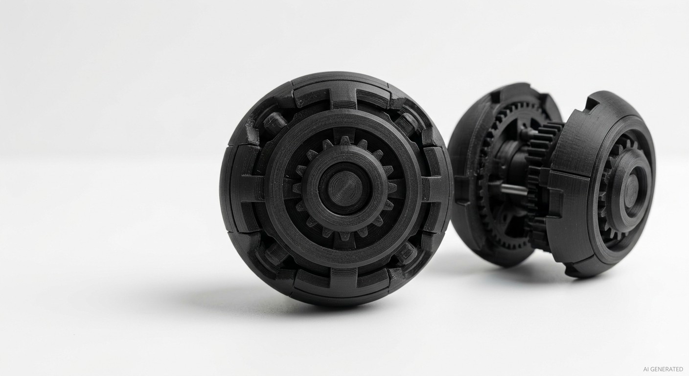
finished 3D printed mechanical fidget ball
This guide covers everything you need to print one successfully: how the mechanism works, what settings actually matter, which filament to use, and how to troubleshoot the problems that catch most people out the first time. The HelixCore fidget ball appears throughout as a concrete example, it's one of the most mechanically ambitious designs in this category, and the lessons from printing it apply broadly to any articulated 3D print of this type.
Here's 10 more 3D printed toys you should try making.
What Is a 3D Printed Fidget Ball?
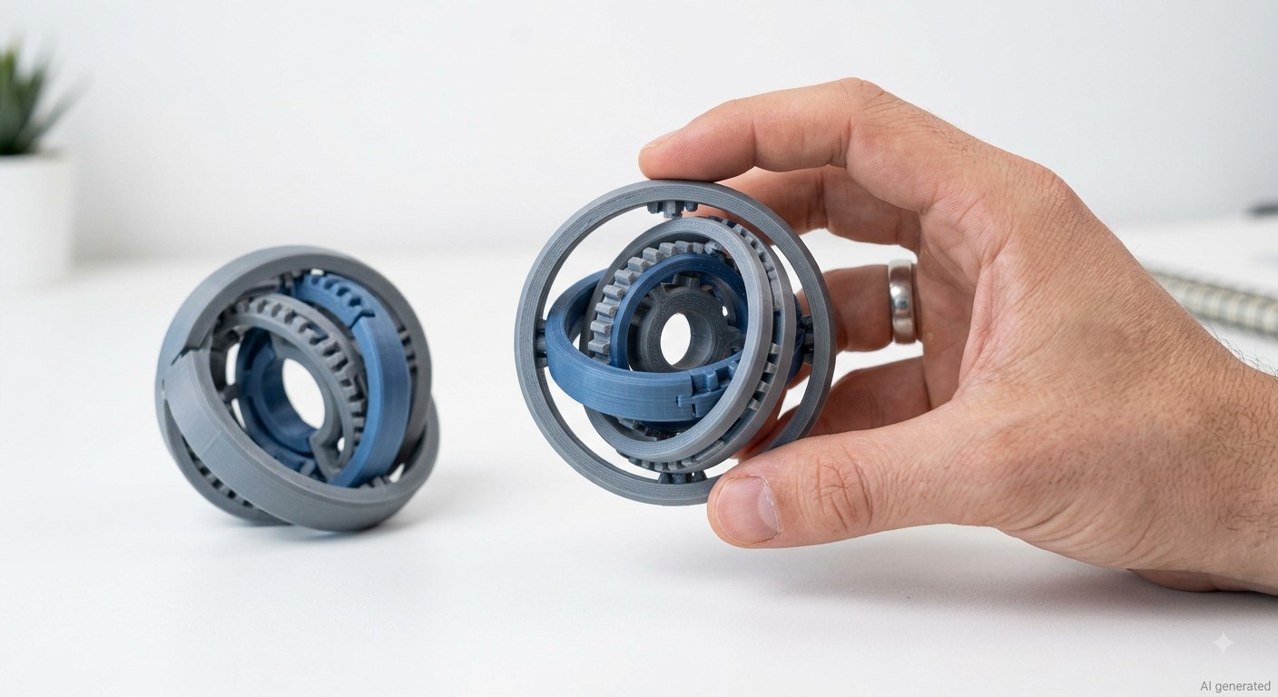
finished print-in-place 3D printed fidget ball
A printed fidget ball is a handheld mechanical toy produced by additive manufacturing, typically FDM, where multiple moving components are printed together in a single build, with designed-in clearances that allow parts to rotate, slide, or compress relative to each other after printing.
The mechanical structure varies by design. Some 3D printed fidget toys use concentric spherical shells that rotate independently. Others use interlocking ring segments. The HelixCore combines a ball screw mechanism, clutch system, elastic return drive, and dual 608 bearings to convert squeezing motion into rotational motion, press one end and the body rotates; release it and the clutch locks. More complex than most fidget ball 3D print designs, but the underlying principles are the same: designed clearances, accurate tolerances, and a printer that can hold both consistently.
What separates a fidget ball 3D print from a traditional plastic toy isn't just the manufacturing process, it's the design freedom. Injection molding requires draft angles, parting lines, and tooling for every unique geometry. 3D printing produces internal moving parts that injection molding physically cannot produce as a single object. A fidget ball 3D print with three rotating internal shells in a single build is genuinely impossible to injection mold as one piece. That's why makers print them.
Why Print-in-Place Fidget Balls Are Popular
Print-in-place 3D printing is what makes most fidget balls possible. The concept is straightforward: instead of printing separate parts and assembling them, the printer builds multiple moving components simultaneously, with controlled gaps between them that allow movement while preventing fusion.
A 0.2–0.4 mm clearance can be a starting point for some desktop FDM print-in-place designs, but it is not a universal tolerance specification. For a deeper explanation of production-ready 3D printing tolerances, see our comprehensive guide to 3D printing tolerances.
The popularity of print-in-place 3D printing for fidget balls comes down to four things:
- Immediate payoff. There's no assembly. The print comes off the bed and works, or doesn't, in which case troubleshooting starts. Either way, you know immediately.
- Mechanical demonstration. A print-in-place fidget ball proves your printer's calibration. If it works smoothly, your flow rate, dimensional accuracy, and first layer are all good. It's a calibration test that's more satisfying than a test cube.
- Design challenge. For makers who design their own models, print-in-place 3D printing is a genuine puzzle, how do you design clearances that survive the specific quirks of a desktop FDM printer, handle thermal expansion as layers cool, and still produce clean movement?
- Shareability. A working 3D printed fidget ball is one of the most immediately impressive things to show someone who's never seen additive manufacturing. The "how is this moving?" reaction is reliable.
What You Need Before Printing a Fidget Ball
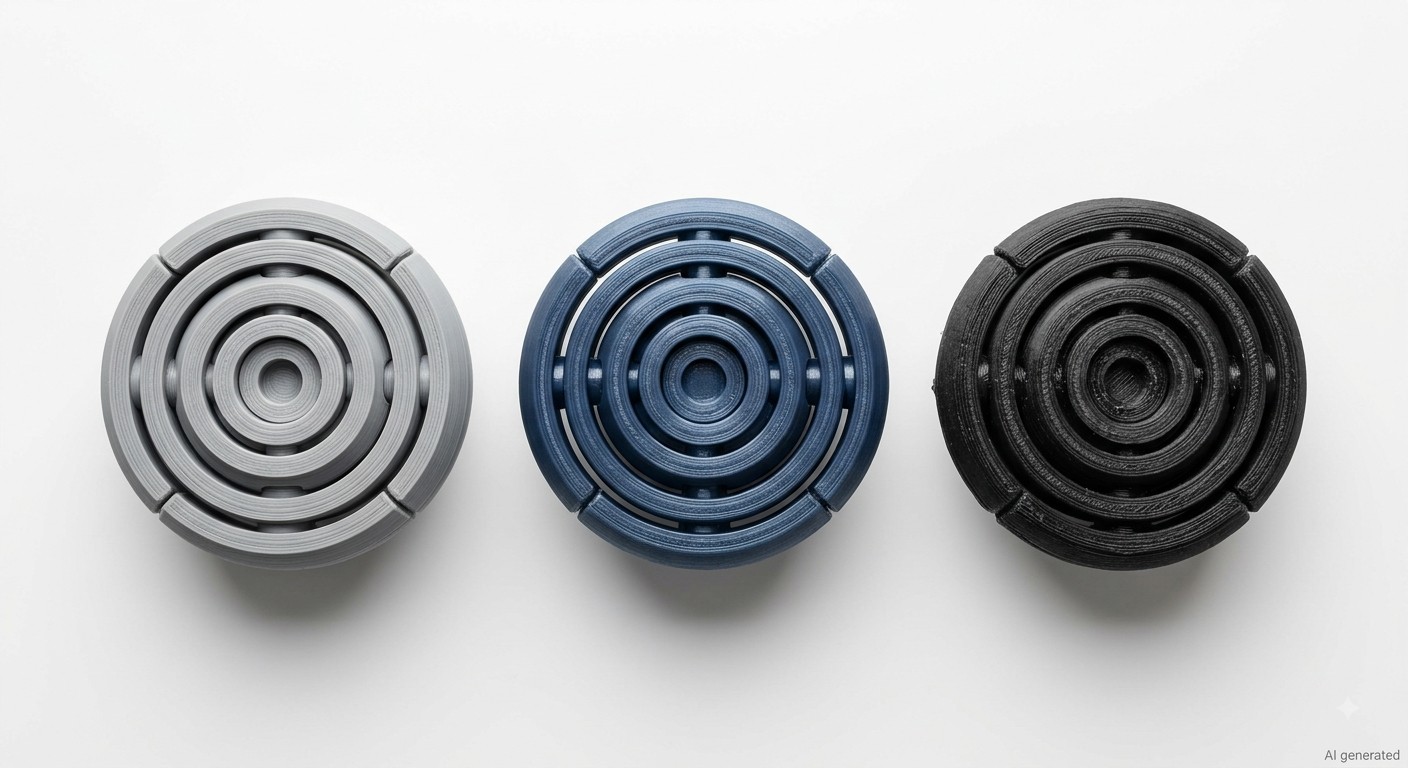
3D printed mechanical fidget balls
3D Printer Requirements
Any reasonably well-calibrated FDM printer handles most fidget ball designs. For 3D printer requirements, they aren't about brand or price point, they're about consistency.
Extrusion consistency matters most. A printer with occasional under-extrusion creates weak layer adhesion between the walls of moving parts, which causes failure during the post-print manipulation that frees stuck components. Over-extrusion causes the opposite problem, parts that should be separate fuse together because excess material bridges the designed clearances.
Bed leveling directly affects first layer quality, which determines whether the bottom of the fidget ball 3D print lifts, warps, or fuses to the build surface. Particularly on larger diameter designs where the build footprint is wide, any bed level variation across the print area affects the first few layers where clearance geometry is established.
Direct drive extruders handle flexible filaments like TPU more reliably than Bowden setups if you're planning to print fidget toys with elastic components. For rigid PLA or PETG builds, either setup works fine.
Calibration
Flow rate calibration is the single most important print preparation step for any articulated 3D print. Print a hollow single-wall calibration cube and measure the wall thickness, it should match your nozzle diameter exactly. If it's 0.45mm when your nozzle is 0.4mm, reduce flow rate by 10%. This step takes 20 minutes and is the difference between a 3D printed fidget ball that works and one that comes off the bed as a solid lump.
Bed leveling using a test print that covers the full build area catches leveling variation that a simple center-point check misses. A 3D printed fidget ball that's 60mm in diameter checks bed level across a 60mm diameter circle, any variation in that area affects the critical first layers.
Recommended Materials
PLA is the default choice for most 3D printed fidget ball projects. It prints at lower temperatures, shrinks minimally, and produces clean surfaces with good dimensional accuracy on calibrated printers. The best filament for fidget toys at beginner level is almost always PLA, it's forgiving, cheap, and available in every color.
PETG is worth considering for designs that will see heavy use. PETG has better impact resistance than PLA and handles the repeated stress of fidget ball mechanisms more durably over time. It requires slightly higher temperatures than PLA and may need slower printing and careful retraction tuning to reduce stringing, but the layer adhesion and toughness improvement over PLA is meaningful for articulated 3D print projects.
TPU works for specific fidget designs that incorporate flexible elements, compressible outer shells or springy retention features. It's not the best filament for fidget toys that require rigid gear or ball screw mechanisms, because the flexibility that makes TPU useful in some contexts introduces unpredictable play into precision mechanical clearances.
A key tip on choosing materials: start with PLA unless the design specifically calls for something else. Get the print working in PLA first, then experiment with other materials once you understand how the specific design behaves.
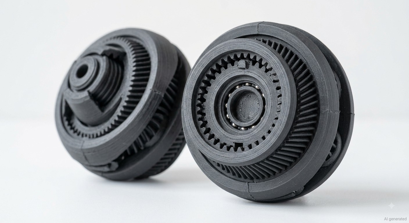
HelixCore-style mechanical fidget ball
Best 3D Printing Settings for Fidget Balls
Practical Note
These settings are starting points for calibrated FDM printers. Actual clearance requirements should be validated on the specific printer, material, and model before production.
| Setting | Recommended Value | Why It Matters |
|---|---|---|
| Layer height | 0.15-0.2mm | Finer layers improve surface finish on curved moving surfaces |
| Nozzle diameter | 0.4mm | Balance between detail and print speed |
| Material | PLA (first choice) / PETG | Dimensional accuracy, surface quality |
| Print speed | 40-60mm/s | Slower = more accurate; critical for clearance geometry |
| Supports | Usually not required | Fidget ball designs are support-free; supports damage clearances |
| Infill | 10-20% | Moving parts don't need structural infill; weight matters for fidget feel |
| Wall count | 3-4 perimeters | Adequate strength without interfering with clearances |
| Cooling | Maximum after first layer | Good cooling prevents sagging into clearance gaps |
| Bed temperature | 60℃ (PLA) / 70-80℃ (PETG) | Adequate adhesion without warping |
| Flow rate | Precisely calibrated, see below | The single most important setting for clearance-dependent prints |
1Layer Height
0.15mm is the better choice for most fidget ball 3D print work. The improvement in surface finish on curved and spherical surfaces at 0.15mm versus 0.2mm is significant, smoother surfaces in the clearance zones mean parts that release more cleanly after printing and move more smoothly in use. The print time increase of 25-35% is the trade-off. For a first attempt at a new design, 0.2mm is acceptable for testing; for a final result, 0.15mm is worth the extra time.
2Nozzle Size
A 0.4mm nozzle handles the clearance geometry in most fidget ball designs adequately. A 0.6mm nozzle speeds prints up but reduces the precision of thin clearance walls, so it is not recommended for mechanical designs where 0.2 - 0.4mm gaps are doing real work. 0.2mm nozzles produce exceptional surface quality but print extremely slowly and clog more easily, making them overkill for most 3D printed fidget toys. For a deeper comparison of nozzle diameters, detail, speed, and strength, see our guide to 3D printing nozzle sizes.
3Supports
For print-in-place designs specifically engineered to be support-free, disable supports whenever possible. Supports placed inside moving clearances can fuse components and make post-processing difficult. Generally many competent fidget ball 3D print designs are engineered to be support-free, with overhangs at 45° or less and bridging spans within the capability of most printers. Adding supports to a print-in-place 3D printing design puts material exactly where the clearance gaps are supposed to be, and the support removal process destroys the geometry it was supposedly protecting. If a fidget ball design requires supports, it was either designed for assembly or wasn't designed well.
How to Print and Assemble a HelixCore Fidget Ball
HelixCore is one of the more mechanically complex options among 3D printed fidget toys, making it a good project for makers who want to explore mechanical FDM printing.
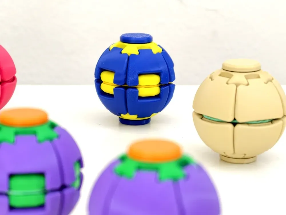
HelixCore on Makerworld (The design by the original creator, YY the panjang).
Unlike simpler print-in-place fidget balls, the HelixCore combines a mechanical mechanism with a small amount of post-print hardware. Its design uses a ball screw mechanism, clutch system, elastic return drive, and dual 608 bearings to convert a squeezing motion into rotation.
The basic interaction is simple: press, spin, and release. However, the tighter mechanical clearances make HelixCore more sensitive to printer calibration, extrusion accuracy, and assembly than a basic fidget ball.
HelixCore Design and Hardware Requirements
The HelixCore's internal mechanism combines four main elements:
- Ball screw mechanism
- Clutch system
- Elastic return drive
- Dual 608 bearings
The designer specifies the following hardware:
- 2 × 608ZZ bearings
- 1 × rubber band
- 608ZZ bearing size: 22 mm outer diameter × 8 mm inner diameter × 7 mm thickness
- No magnets required
- No glue required
The designer has successfully tested rubber bands ranging from 28 mm to 40 mm. Different band sizes and strengths change the feel of the mechanism: softer bands provide a lighter squeeze, while stronger or tighter bands provide a faster rebound.
The June 2026 update also added a travel stop behind each segment to keep the segments centered during compression. This change was intended to improve spin consistency and make the mechanism smoother and more reliable.
Note
The hardware and mechanism specifications above come from the HelixCore designer's published description. The printing recommendations in the following sections are general or article-specific recommendations rather than designer-specified requirements.
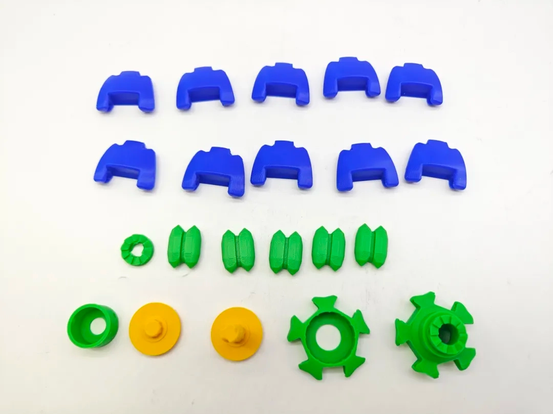
JLC3DP PLA HelixCore fidget ball full model parts
Choose a HelixCore 3D Print Profile
HelixCore provides several print-profile options for different assembly and appearance requirements.
-
Standard Edition (Fast Assembly)
The Standard Edition is designed for most users. Its shell components are grouped together to reduce the number of printed parts and shorten assembly time while maintaining the intended spinning performance.
The designer notes that the Standard profile still requires the correct orientation during assembly because the upper shell, lower shell, and hinge are printed together as one part.
-
Color Custom Edition – Classic
The Classic version uses the original multicolor shell layout shown in the cover images. It is intended for users who want custom color combinations while maintaining the original visual proportions.
-
Color Custom Edition – Enhanced
The Enhanced version uses larger accent panels and stronger visual contrast for more prominent color combinations.
The updated Color Custom version also uses identical, interchangeable petals, which simplifies HelixCore assembly by removing the need to install individual petals in a specific orientation.
Prepare and Slice the HelixCore Model
Start with the general 3D printing settings for fidget balls discussed earlier in this guide rather than creating a separate HelixCore printing settings table.
For HelixCore, pay particular attention to the following during slicing:
- Model orientation: Use the orientation provided by the selected print profile.
- Clearance areas: Preview the layers around the ball screw and moving interfaces.
- Flow calibration: Make sure your extrusion is accurately calibrated before printing.
- Supports: Use the supplied profile and avoid adding supports into designed clearance areas.
- Scale: For a first print, use the designer-provided model at its original scale unless the designer provides specific scaling guidance.
In the slicer preview, the clearance between the moving components should remain visibly open. If a designed gap appears filled with extrusion, check your flow calibration and model scale before starting the print.
For the nozzle choice, a 0.4 mm nozzle remains a practical starting point for this type of mechanical geometry. If you want to understand how nozzle diameter affects detail, speed, and clearance, see our guide to 3D printing nozzle sizes.
Assembly Tips
After printing, allow the part to cool before removing it from the build plate to reduce the risk of deformation.
HelixCore requires some manual manipulation during assembly and initial operation. When freeing the mechanism, apply gradual pressure while rotating rather than forcing the parts suddenly.
-
Allow Part to Cool Before Removal
After printing, allow the part to cool before removing it from the build plate to reduce the risk of deformation.
HelixCore requires some manual manipulation during assembly and initial operation. When freeing the mechanism, apply gradual pressure while rotating rather than forcing the parts suddenly.
-
Install the 608ZZ Bearings
Install the two specified 608ZZ bearings and make sure they are seated correctly. Incorrect bearing placement can affect alignment and rotation.
-
Install the Rubber Band
Use a suitable rubber band within the designer's tested 28–40 mm range. Softer bands provide a lighter squeeze, while stronger or tighter bands provide a faster rebound.
-
Check the Assembly Orientation
HelixCore assembly requirements depend on the selected print profile.
The Standard profile requires the correct orientation because several shell components are printed together. The updated Color Custom version uses interchangeable petals, making assembly less orientation-sensitive.
-
Lubricate the Clutch Contact Surfaces
The designer specifically recommends applying a small amount of grease or light lubricant to the clutch contact surfaces during assembly.
This can improve the smoothness and consistency of the mechanism.
Avoid excessive lubricant, which can collect dust or affect the fit of moving components.
Optional Flywheel Weights
HelixCore includes a built-in weight pocket on the back of each hinge.
The pocket is sized for M5 nuts by default. Adding weight increases rotational inertia and can extend the duration of the spin.
The flywheel system is optional. HelixCore is designed to function with or without additional weights.
The weight pockets can also be customized using negative parts if you want to use a different nut size.
Common Fidget Ball Printing Problems and Solutions
Print-in-place fidget balls depend heavily on accurate extrusion, dimensional consistency, first-layer control, and designed clearances. The same problems can affect both simple fidget balls and more complex mechanisms such as HelixCore.
1Why Are the Parts Stuck Together?
Fused or stuck components are usually caused by excessive material entering the designed clearance.
The most common causes are:
- Over-extrusion: Excess material bridges the clearance gaps.
- Incorrect scaling: Scaling down reduces the designed gap proportionally.
- First-layer squish: Excessive first-layer compression can fuse moving components near the build plate.
Start by checking your flow calibration and printer dimensional accuracy. If the single-wall calibration result is larger than the expected wall thickness, correct the flow before printing the mechanism again.
For mechanical fidget balls, avoid changing the model scale unless the designer explicitly provides scaling guidance. Scaling can change the clearance relationship between moving components.
If the first layer is excessively squashed, adjust the Z offset and verify the first-layer appearance before attempting another print.
For HelixCore specifically, also inspect the ball screw and clutch areas in the slicer preview before printing.
2Why Doesn't the Fidget Ball Move Smoothly?
Rough movement is often caused by surface irregularities inside the designed clearance zones. Layer lines can increase friction between adjacent moving surfaces.
Start by gently moving the mechanism after printing to help release the moving interfaces. Do not apply sudden force to a mechanism that is still partially fused.
If the problem is caused by insufficient clearance rather than surface texture, repeated movement will not solve it. Check your flow calibration and slicer settings and reprint if necessary.
For HelixCore, also check the clutch contact surfaces and follow the designer's recommendation to apply a small amount of grease or light lubricant during assembly.
3Why Is the Spin Inconsistent?
Inconsistent rotation can result from several factors:
- Incorrect assembly orientation
- Misaligned bearings
- Inconsistent clearance
- Incorrect rubber-band tension
- Rough clutch contact surfaces
- Poor printer calibration
For HelixCore, verify that the selected print profile has been assembled correctly and that the two 608ZZ bearings are properly seated.
The designer's June 2026 update added a travel stop behind each segment to keep the segments centered during compression, specifically improving spin consistency.
If the mechanism still spins inconsistently, inspect the clutch surfaces and rubber-band tension before changing the model itself.
4Why Did the Print Fail?
Long or relatively tall fidget-ball prints can be vulnerable to layer shifts, vibration, and poor bed adhesion.
Potential causes include:
- Insufficient first-layer adhesion
- Excessive print speed
- Printer vibration
- An unstable printer frame
- Poor build-surface cleanliness
A 3–5 mm brim can increase the first-layer contact area when additional stability is needed. Reducing print speed can also help reduce mechanical vibration during tall prints.
For PLA and PETG, keeping the build surface clean is also important for reliable first-layer adhesion.
Can You Make a Fidget Ball Without Owning a 3D Printer?
Yes, and for many users, this is actually the better path to a well-executed 3D printed fidget ball.
Desktop FDM printing produces excellent results when the printer is well-calibrated and the user understands the settings. But getting to that point involves calibration time, failed prints, filament changes, and troubleshooting sessions that can turn a weekend project into a weeks-long learning curve. The fidget ball print settings in this guide work, but they assume a calibrated printer, which is a prerequisite that takes time to achieve.
Professional 3D printing services remove those variables. The equipment is production-grade, consistently calibrated, and operated by people who've resolved the calibration questions that trip up beginners. If you want a HelixCore fidget ball that works the first time, or if you want to produce several of the same design in consistent quality, an online printing service often produces better results faster than doing it yourself.
JLC3DP's FDM 3D printing service handles PLA, PETG, ABS, and engineering-grade materials on industrial equipment, with instant quoting from uploaded STL files. For articulated 3D print designs like fidget balls where tolerances are everything, production equipment with verified calibration produces consistently better clearance geometry than an uncalibrated desktop printer, particularly for complex mechanical designs like the HelixCore fidget ball.
If you're printing 3D printed fidget toys for a group, making multiples of the same design, or attempting an advanced mechanical fidget ball for the first time, uploading the STL and getting it printed professionally often makes more sense than managing the desktop printing process yourself.
FAQ About 3D Printed Fidget Balls
Q: What is the best filament for 3D printed fidget balls?
PLA is the best filament for fidget toys for most makers, it prints accurately, shrinks minimally, and produces clean surface finish in clearance zones. PETG is a good upgrade for durability once you've confirmed the design works in PLA. Avoid TPU for mechanical fidget ball designs with gears or screw mechanisms.
Q: How much clearance for a print-in-place fidget ball?
A 0.2–0.4 mm clearance is a practical starting range for some FDM print-in-place fidget balls, but it is not a universal tolerance. The required clearance depends on the printer, material, geometry, and calibration. Always validate the clearance on your specific setup before printing the full mechanism.
Q: Why are the parts of my fidget ball fused after printing?
Fused parts in a print-in-place 3D printing project are almost always caused by over-extrusion or incorrect scaling. Calibrate your flow rate using a single-wall test cube, confirm your printer's dimensional accuracy, and print at 100% scale unless the designer specifies otherwise. Reducing flow rate by 5% and reprinting resolves most fused-part failures.
Q: Do 3D printed fidget balls need supports?
No, competent fidget ball 3D print designs are engineered to be support-free. Adding supports to a print-in-place fidget ball damages the clearance geometry and makes the print worse, not better. If a design requires supports for a fidget ball, it's either an assembly design or wasn't optimized for print-in-place production.
Q: How long does a 3D printed fidget ball take to print?
Print time depends on design size and complexity. A simple fidget ball 3D print at 50-60mm diameter in PLA at 0.2mm layer height typically takes 3-5 hours. The HelixCore fidget ball at 0.15mm layer height runs 6-10 hours depending on printer speed. Reducing layer height to 0.15mm adds roughly 30-40% to print time versus 0.2mm.
Q: Can I scale down a fidget ball design to print faster?
Generally no, scaling down a mechanical fidget ball 3D print compresses the designed clearances proportionally, often below what desktop FDM printers can reliably produce as a clean air gap. The HelixCore designer specifically warns against scaling for this reason. Print at 100% scale and adjust the slicer settings (primarily speed and layer height) to improve quality rather than scaling geometry.
Q: What makes the HelixCore different from other fidget balls?
The HelixCore fidget ball combines a ball screw mechanism with a one-way clutch, a level of mechanical complexity that goes beyond typical print-in-place 3D printing designs. Most 3D printed fidget toys use simple rotation or shell nesting. The HelixCore translates pressing motion into rotation while the clutch prevents reverse movement, creating a unique action that no simpler design replicates.
Keep Learning
15 Tips for Fast 3D Printing
3D printing can be time-consuming, but there are some strategies to speed up the process without sacrificing too much quality. Below are 15 practical tips to speed up your 3D printing process while maintaining decent quality. These tips are especially useful for prototyping or when speed is a priority: 1. Increase Layer Height ● Why: Thicker layers mean fewer layers overall, reducing print time. ● How: Adjust the layer height in your slicer settings. For example, go from 0.2mm to 0.3mm or higher. ● Tr......
How to prevent 3d printing warping problems
3d printing warping is one of the most common problems faced by 3d printing enthusiasts. Especially when printing larger models, the printed parts initially adhere to the print bed, but then the edges of the prints lift off the print bed and curl, causing the model to deform and waste material. The main reason for warping is that plastic materials cool and shrink when printed, which causes deformation. This article will analyze the causes of warping and use suggestions to prevent 3d printing warping t......
How to 3D Print Wood
3D printing has revolutionized the manufacturing industry by allowing the creation of complex and customized objects. While 3D printing with plastic and metal has been widely adopted, the ability to 3D print with wood has opened up new possibilities for creating aesthetically pleasing and environmentally friendly products. In this article, we will explore the process of 3D printing with wood and the techniques involved in achieving the desired results. Understanding Wood Filament The key to 3D printin......
Design for Manufacturing (DFM): 7 Principles, Process & Practical Guide
Key Takeaways Design for Manufacturing (DFM) is a design strategy that connects product requirements with manufacturing capabilities. A successful DFM approach requires choosing the right process, simplifying designs, reducing unnecessary complexity, and considering production volume from the beginning. Different manufacturing methods have unique design considerations. By applying DFM principles early, engineers can reduce redesign risks, improve product quality, shorten production cycles, and create ......
3MF VS STL: Which File Format Is Better for 3D Printing?
In the additive manufacturing industry, the STL format has served as the de facto standard for decades. However, the rapid evolution of modern 3D printing has highlighted its technical limitations. Consequently, the 3MF format—backed by an industry consortium including Microsoft, HP, and Ultimaker—has emerged as a robust, next-generation alternative. When exporting a 3D model from CAD or preparing it within a slicer, understanding the technical nuances of 3MF VS STL is critical. This article provides ......
Design for Additive Manufacturing: A Practical DfAM Guide
Key Takeaways DfAM is not DFM: Design for additive manufacturing focuses on exploiting AM's geometric freedom rather than simply simplifying parts. Build orientation matters: Orientation affects strength, surface finish, supports, thermal distortion, and overall cost. Design for the process: Wall thickness, overhangs, holes, clearances, and tolerances must match the specific AM technology and material. Complexity can reduce cost: Part consolidation, lattices, and internal channels can deliver value th......