3D Printing for Rapid Prototyping: Pick the Right Tech, Material & Budget
21 min
- What Is Rapid Prototyping with 3D Printing?
- Rapid Prototyping vs Traditional Manufacturing
- Rapid Prototyping Development Process
- Why Use 3D Printing for Rapid Prototyping?
- Which 3D Printing Technology Is Best for Rapid Prototyping?
- How to Choose the Right Material for Your Prototype
- Design Tips for Better Rapid Prototypes
- Common Design Mistakes to Avoid
- How Much Does a Rapid Prototype Cost?
- Where Is Rapid Prototyping Used?
- FAQ About Rapid Prototyping with 3D Printing
- Conclusion: Choosing the Right Rapid Prototyping Solution
Rapid prototyping with 3D printing lets engineers turn a CAD file into a physical part in days instead of weeks. No tooling. No minimum order quantities. No waiting for a machine shop to fit your job into the schedule. Just a design file and a printed part you can hold, test, and iterate on before committing to expensive production tooling.
That's the core value proposition. But additive manufacturing prototyping isn't a single process, it's a family of technologies, each suited to different prototype objectives. Choosing the wrong technology for your prototype type produces poor results regardless of how good the design is. Choosing the right one produces functional, accurate prototypes that actually accelerate development.
This guide explains how rapid prototyping with 3D printing works, compares the leading technologies and materials, and shares practical design tips to help you produce prototypes faster, more accurately, and at lower development cost.

- Industrial Resin, Nylon, Plastics and Metal 3D Printing.
- From $0.30 — No minimum order quantity.
What Is Rapid Prototyping with 3D Printing?
Rapid prototyping with 3D printing is the process of using additive manufacturing technologies to produce physical models, functional prototypes, and engineering validation parts directly from digital CAD files. Unlike traditional manufacturing methods, it does not require molds, tooling, or dedicated production setup before a part can be made.
The term \"rapid\" distinguishes this approach from traditional prototype manufacturing methods such as CNC machining, injection molding, or casting, which often involve longer preparation steps before a prototype can be produced. By building parts directly from digital designs, 3D printing enables prototypes to be manufactured without dedicated tooling, making it a widely adopted approach throughout modern product development.
Rapid Prototyping vs Traditional Manufacturing
| Factor | Traditional Manufacturing | Rapid Prototyping with 3D Printing |
|---|---|---|
| Lead time | 2-12 weeks | 24-96 hours |
| Tooling required | Often $5,000-50,000+ | None |
| Setup cost | High, regardless of quantity | Minimal |
| Minimum quantity | Often 50-500+ pieces | 1 piece |
| Design change cost | High, tooling modification | File revision only |
| Geometry restrictions | Significant | Very low |
| Materials available | Very broad | Growing but more limited |
| Per-piece cost at prototype quantity | Very high | Competitive |
Rapid Prototyping Development Process
-
Concept & Sketching
Define the product concept and create initial sketches to guide the design direction.
-
CAD Design
Create a detailed 3D model using CAD software, defining all geometry and features.
-
3D Print Rapid Prototype (Appearance Model)
Print an initial prototype for visual review, form checking, and stakeholder feedback.
-
Design Iteration
Refine the design based on feedback from the appearance model before moving to functional testing.
-
Functional Prototype (Engineering Materials)
Print a functional prototype using engineering-grade materials for mechanical testing.
-
Engineering Validation Testing
Test the functional prototype under real-world conditions to verify performance requirements.
-
Pilot Production / Bridge Manufacturing
Produce a small batch for field testing, regulatory approval, or bridging to full production.
-
Production Tooling
Commission production tooling only after the design has been fully validated through prototyping.
-
Volume Manufacturing
Transition to volume production with confidence that the design has been thoroughly tested.
3D printing prototype production is most valuable in the early stages of this cycle, where the design is changing, where discovering problems is cheap, and where committing to tooling would be premature. Rapid prototyping with 3D printing doesn't replace volume manufacturing; it front-loads the discovery of design problems to the stage where fixing them is fast and inexpensive.
Why Use 3D Printing for Rapid Prototyping?
Engineers choose 3D printing for rapid prototyping because it enables faster iteration, reduces development costs, removes many design constraints, and shortens product development cycles. Compared with traditional manufacturing methods, design revisions require only an updated CAD file instead of new tooling, allowing engineering teams to validate concepts and refine designs much more efficiently.
1Faster Design Iteration
Traditional manufacturing links every major design revision to tooling changes, making iteration both time-consuming and expensive. With 3D printing, engineers can simply update the CAD model and produce a revised prototype, allowing more design iterations within the same development schedule and reducing the risk of costly design issues later in the project.
2Lower Development Costs
The primary cost advantage of rapid prototyping is not lower manufacturing cost per part. Instead, it comes from reducing overall product development costs. Early design validation minimizes expensive engineering changes, avoids unnecessary tooling investment before the design is finalized, and allows teams to identify problems before they affect production.
3Greater Design Freedom
Additive manufacturing prototyping builds geometry from the inside out, internal channels, lattice structures, undercuts, and complex organic shapes all exist within the design freedom envelope of 3D printing. CNC machining prototype work is constrained by tool access; injection molding prototyping is constrained by draft angles, parting lines, and moldability. Rapid prototyping with 3D printing reduces these geometric constraints dramatically, particularly for internal features that machining can't reach.
4Faster Time-to-Market
Because prototypes can be produced and revised much faster, engineering teams complete more validation cycles within the same project timeline. Earlier problem discovery reduces redesign delays and helps products reach production sooner.
Which 3D Printing Technology Is Best for Rapid Prototyping?
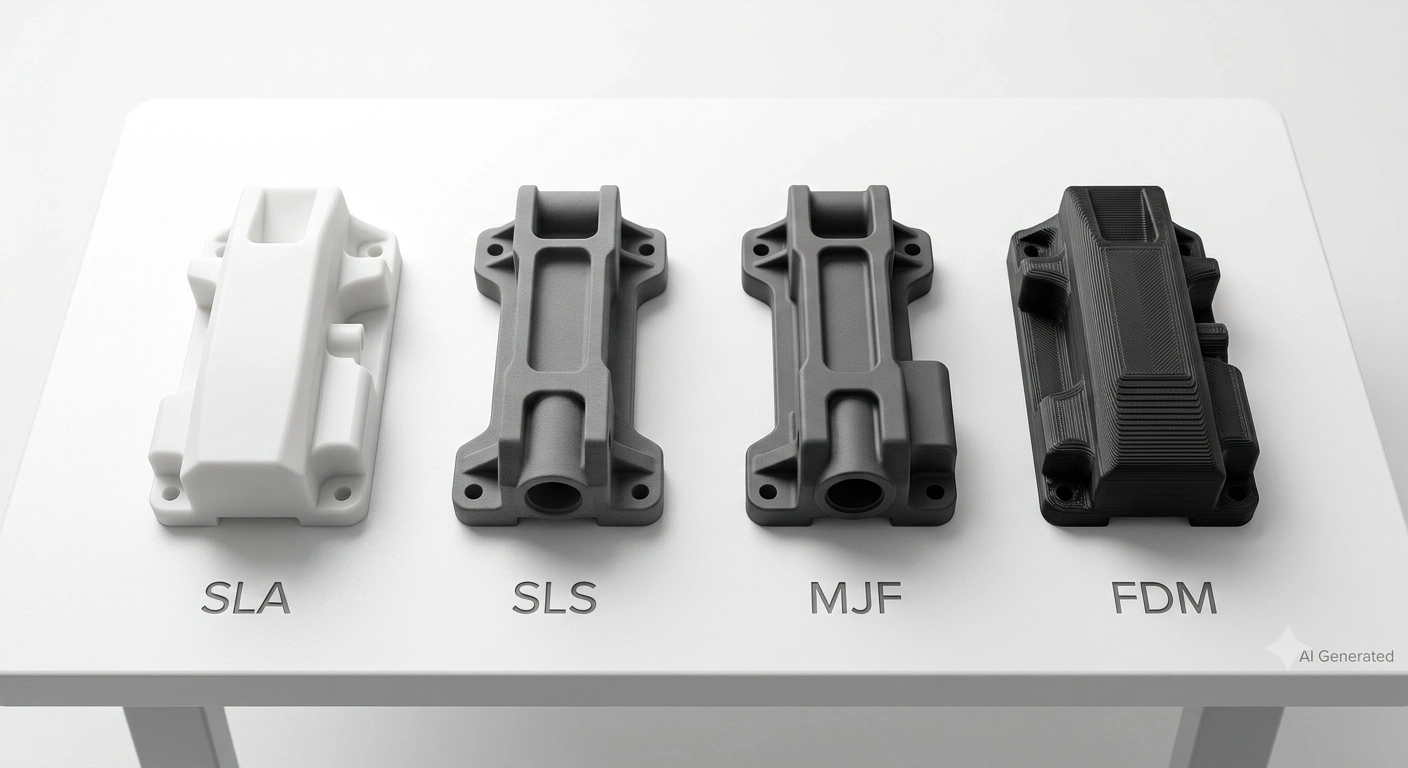
There is no universally best rapid prototyping technology. The right choice depends on the prototype's purpose, appearance modeling, functional testing, engineering validation, or end-use component production, and the specific requirements for surface finish, mechanical properties, dimensional accuracy, and cost.
SLA for High-Detail Visual Models
SLA rapid prototyping uses a UV laser to cure liquid photopolymer resin layer by layer, producing parts with the best surface finish of any common rapid prototyping technology. SLA prototypes come off the machine with a smooth, near-injection-molded appearance that requires minimal post-processing for presentation models.
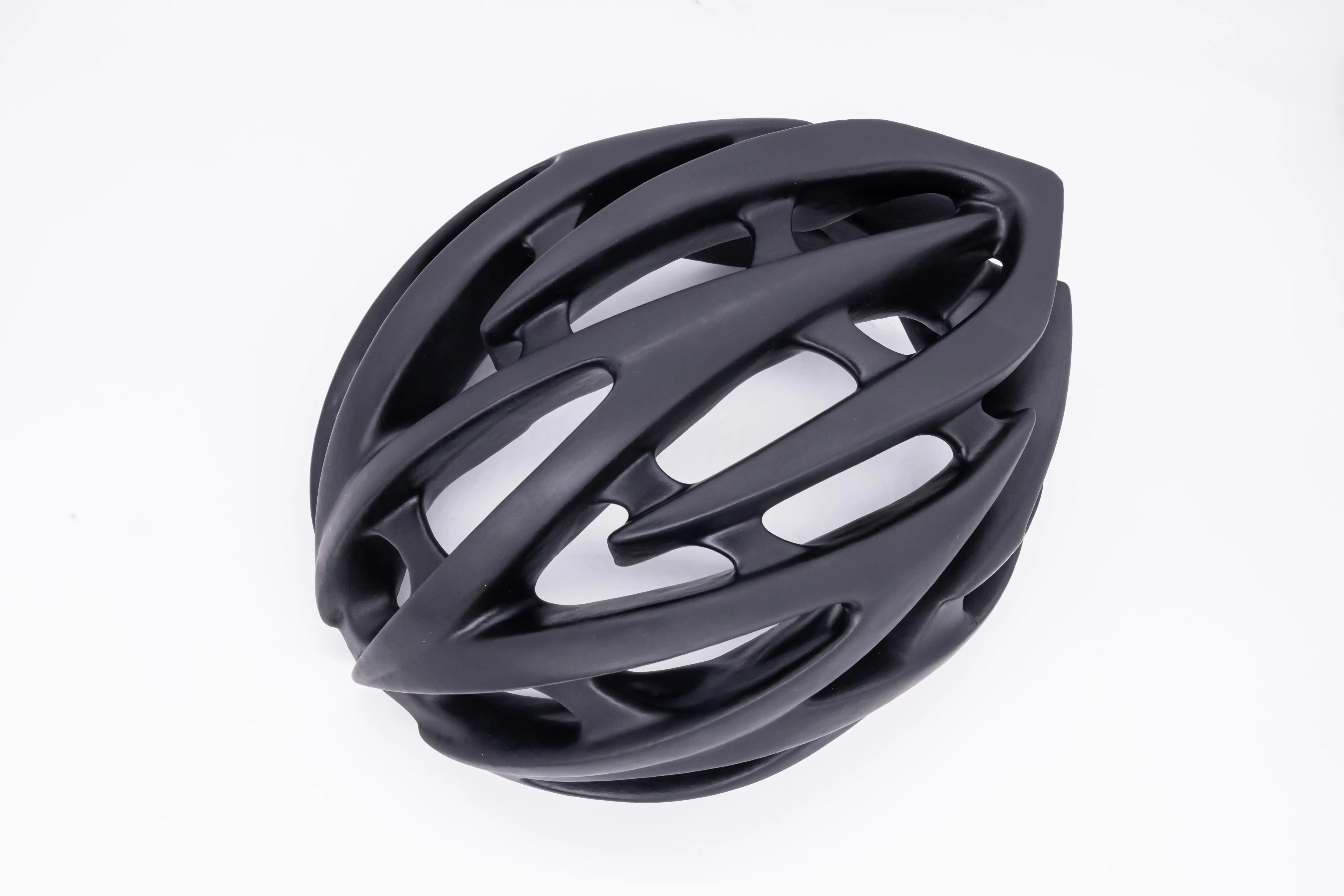
SLA prototype work suits appearance models, presentation parts, form and fit checking, clear or transparent components, and any prototype where visual quality is the primary requirement. However, because the process is optimized for surface quality rather than mechanical performance, SLA is generally less suitable for demanding functional testing.
If appearance, transparency, or extremely fine details matter, see our complete guide to SLA 3D Printing.
SLS Prototype for Functional Prototypes
SLS rapid prototyping uses a laser to sinter powdered nylon layer by layer. No support structures are needed, surrounding unfused powder supports the part during printing, which is why SLS handles complex geometry, interlocking assemblies, and thin internal features that other technologies require support removal to produce.

SLS is widely used for functional prototypes because it produces durable parts without support structures, making it well suited for complex assemblies, moving mechanisms, and intricate internal features. It is a common choice when prototypes need to withstand functional testing while maintaining good dimensional stability.
Our SLS 3D Printing guide explains how powder-bed fusion creates strong functional nylon parts without support structures.
HP MJF Prototype for Engineering Validation
MJF (Multi Jet Fusion) is HP's industrial powder-bed fusion technology for producing high-performance nylon prototypes. By selectively depositing fusing and detailing agents before infrared fusion, MJF delivers highly consistent mechanical properties, excellent dimensional accuracy, and a smoother surface finish than conventional SLS. As a result, it is widely used for engineering validation, functional testing, and production-intent prototypes.
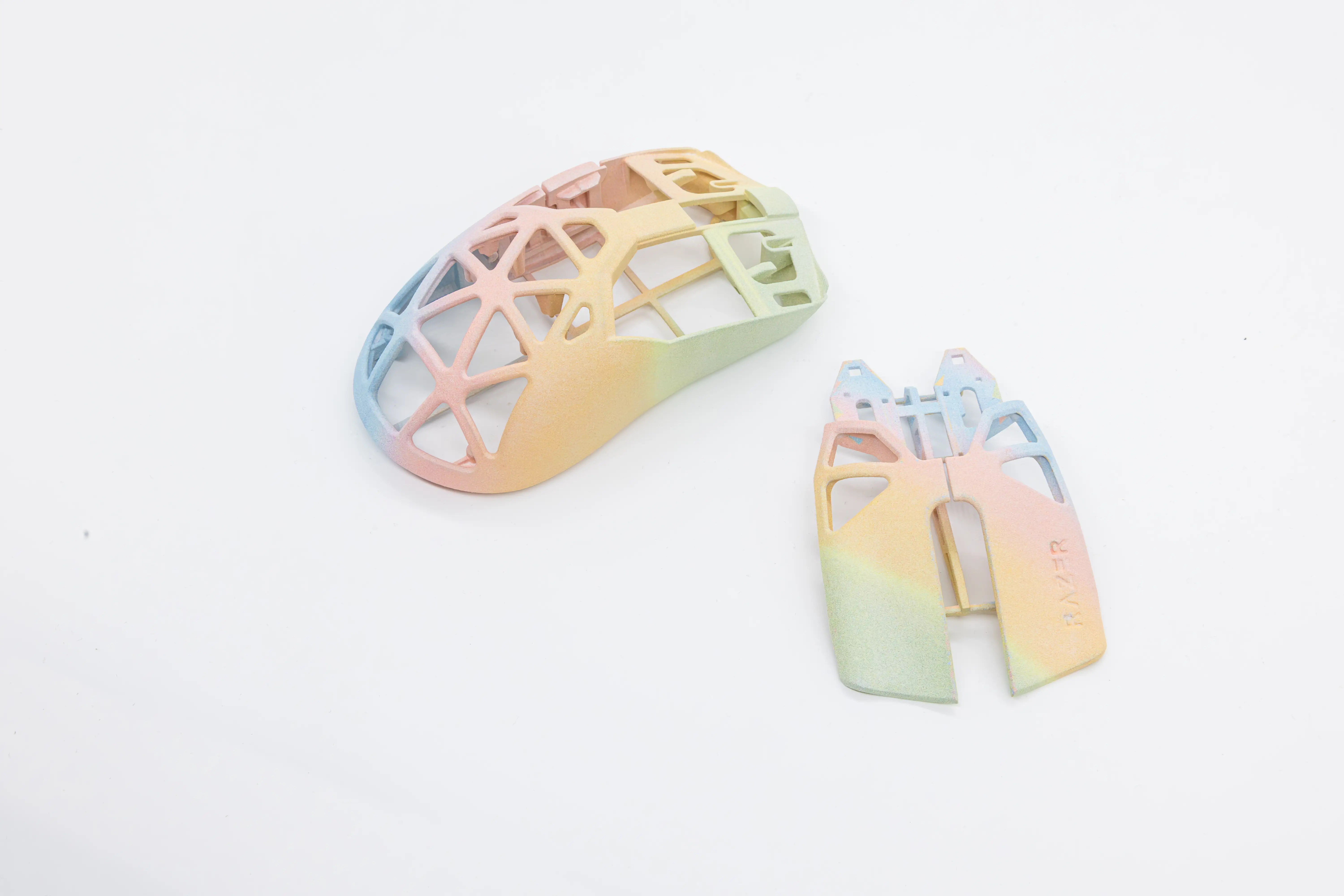
MJF is commonly selected for engineering validation because it combines high dimensional consistency, good surface quality, and repeatable part performance. It is well suited for assembly verification, functional testing, and production-intent prototypes where consistency across multiple parts is important.
If you're comparing industrial nylon technologies, read our detailed MJF vs SLS comparison before selecting a process.
FDM Prototype for Cost-Sensitive Iterations
FDM (Fused Deposition Modeling) extrudes melted thermoplastic layer by layer, the most accessible and least expensive rapid prototyping with 3D printing technology. FDM prototype parts show visible layer lines and have anisotropic mechanical properties (weakest in the layer direction), which limits their use for functional mechanical testing.

Where FDM prototype production excels is early-stage form and fit checking, internal review models, and any prototype where the design is likely to change significantly and per-piece cost matters more than surface quality or mechanical accuracy. An FDM prototype is the right tool for a concept that hasn't been validated yet.
Metal 3D Printing for End-Use Components
Metal 3D printing using SLM or binder jetting enables complex metal geometries that would be difficult or expensive to machine conventionally. It is commonly used for functional metal prototypes and low-volume end-use components in aerospace, automotive, medical, and industrial applications.
Metal rapid prototyping is significantly more expensive than polymer processes but competes favorably against CNC machined metal prototypes for complex geometry where machining would require many setups or custom tooling.
| Technology | Accuracy | Surface Finish | Mechanical Strength | Relative Cost | Best Applications |
|---|---|---|---|---|---|
| SLA | ±0.2mm (Within 100mm), ±0.3% (Above 100mm) | Excellent (smooth) | Moderate | Medium | Visual models, clear parts, detailed presentation prototypes |
| SLS | ±0.3mm (Within 100mm), ±0.4% (Above 100mm) | Good (slightly rough) | Good-Excellent | Medium | Functional prototypes, complex geometry, no supports needed |
| MJF | ±0.3mm (Within 100mm), ±0.4% (Above 100mm) | Very Good | Excellent | Medium | Engineering validation, production-intent nylon parts |
| FDM | ±0.3mm (Within 100mm), ±0.4% (Above 100mm) | Moderate (layer lines) | Moderate | Low | Early-stage iterations, form models, cost-sensitive projects |
| Metal SLM/BJ | SLM: ±0.3mm (Within 100mm), ±0.4% (Above 100mm) BJ: ±0.3mm or ±0.4% (for model size ≤50mm); ±1.3% (for model size>50mm) |
Moderate-Good | Excellent | High | Functional metal prototypes, end-use components |
How to Choose the Right Material for Your Prototype
Material selection for rapid prototyping with 3D printing should be driven by what the prototype needs to do, not what's cheapest or most familiar. A material that's wrong for the testing objective produces prototype results that don't predict production performance, which defeats the purpose of making the prototype.
When selecting a prototype material, start with the engineering question you need to answer rather than the material itself. If appearance is the priority, choose resin. If functional testing is required, nylon is typically the best starting point. For flexible parts, TPU is the preferred option, while metal alloys are reserved for applications that require production-level strength, thermal performance, or regulatory validation.
Resin Prototype Materials
Standard SLA resins produce the best surface finish of any rapid prototyping material and are appropriate for visual models, presentation prototypes, and clear component prototyping. Engineering resins extend the application to higher-temperature environments and improve toughness. The material limitation for resin rapid prototyping is long-term mechanical durability, resins degrade under UV and don't have the fatigue resistance of engineering thermoplastics.
ABS Rapid Prototype Materials
ABS in FDM rapid prototyping produces parts that are familiar to engineers from injection-molded ABS products, similar stiffness, similar impact behavior, similar surface feel. FDM ABS prototype parts are appropriate for form checking, early-stage function testing, and internal review models. The layer-direction weakness of FDM ABS means it shouldn't be used for structural testing where the load direction coincides with the build direction.
Compared with nylon, ABS is easier and more economical to prototype but offers lower fatigue resistance and reduced durability for demanding mechanical applications.
Nylon Prototype Materials
PA12 is available in SLS and MJF. PA12 nylon rapid prototyping is the go-to material for functional prototype testing that needs to simulate production plastic part performance. Nylon prototype parts handle the impact, fatigue, and environmental conditions of functional testing better than any other common rapid prototyping material. For engineering prototypes that will be tested rather than just looked at, nylon is the default starting material in most engineering disciplines.
Compared with SLA resins, nylon provides significantly better toughness and fatigue resistance. Compared with ABS, it generally offers better wear resistance and dimensional stability, making it the preferred choice for engineering validation and moving assemblies.
TPU for Flexible Prototypes
TPU in FDM or SLS rapid prototyping produces flexible, rubber-like parts for seals, gaskets, grips, cable covers, and other components where flexibility is the functional requirement. The TPU prototype material range spans Shore 85A to 95A hardness in most rapid prototyping services, covering most flexible component application requirements.
Because of its elasticity, TPU is not suitable for rigid structural components or prototypes requiring high dimensional stability under load. It is typically selected only when flexibility is a functional requirement.
Metal Prototype Materials
Metal rapid prototype materials through SLM include 316L stainless steel, and Ti-6Al-4V titanium, the most commonly used engineering alloys in aerospace, medical, and industrial prototype applications. Metal rapid prototyping material properties approach those of conventionally manufactured equivalents in most mechanical parameters, making metal 3D printing genuinely appropriate for end-use component validation.
| Material | Strength | Heat Resistance | Surface Quality | Flexibility | Best Prototype Application |
|---|---|---|---|---|---|
| Standard Resin (SLA) | Moderate | Low (50-60°C) | Excellent | Low | Visual models, presentation parts |
| Engineering Resin (SLA) | Good | Moderate (80-100°C) | Excellent | Low-Moderate | Appearance + moderate function |
| ABS (FDM) | Moderate | Good (98°C) | Moderate | Low | Form and fit, cost iterations |
| PA12 Nylon (MJF/SLS) | Good | Good (175°C) | Good-Very Good | Moderate | Functional prototypes, mechanism testing |
| TPU (FDM/SLS) | Moderate | Moderate | Moderate | High | Flexible components, seals, grips |
| Stainless Steel (SLM) | Excellent | Excellent (500℃+) | Good | None | Functional metal prototypes |
| Titanium TC4 (SLM) | Excellent | Excellent (500℃+) | Good | None | Functional metal prototypes |
Design Tips for Better Rapid Prototypes
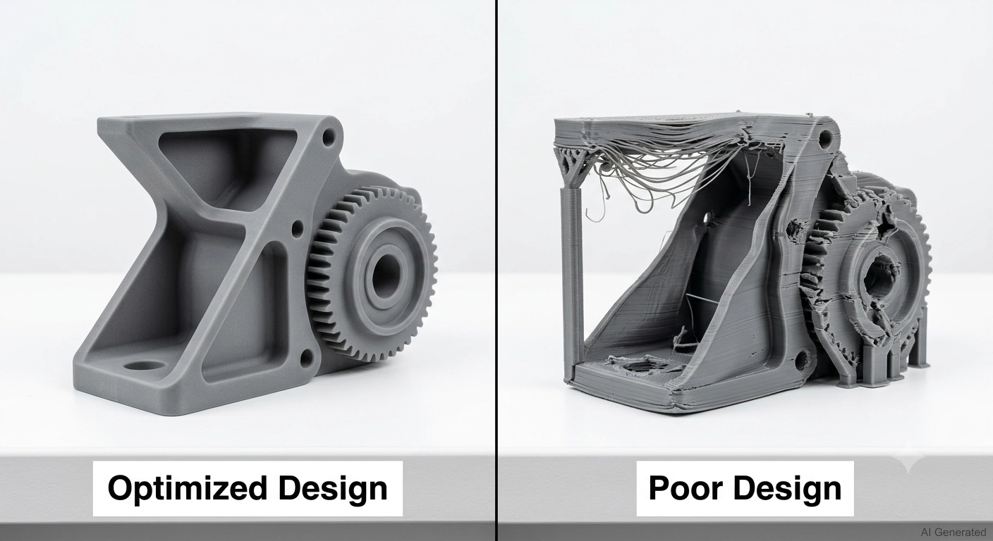
Good design for rapid prototyping reduces cost, improves print success rate, and produces prototypes that more accurately represent production intent. The design rules vary by technology, but the underlying principles are consistent.
Minimum Wall Thickness
Walls below these minimums either fail to print or produce fragile features that break during post-processing or handling. Design walls with margin above the minimum for the technology being used. Check our wall thickness design guide for process-specific requirements before finalizing rapid prototyping designs.
| Technology | Minimum Wall Thickness |
|---|---|
| SLA | 0.8mm |
| SLS / MJF | 1.0mm |
| FDM | 1.2mm |
| Metal SLM | 1.5mm |
Tolerances
3D printing prototype tolerances vary based on the technology selected, part structure, and dimensions, typically ranging from ±0.1 to ±0.5mm. Don't design rapid prototype assemblies to the same clearances as injection-molded production parts, the process tolerances are different.
When designing mating parts, always include appropriate clearance to account for the manufacturing tolerance of the selected process.
Support Structures
SLA, FDM, and metal SLM require support structures for overhanging features. To reduce support marks, minimize post-processing, and shorten print time, avoid unnecessary horizontal overhangs, use chamfers where possible, and orient the model to reduce supported areas. Support requirements vary by process, so review the design guidelines before finalizing your model.
Part Orientation
Orientation affects surface finish, strength, support requirements, and build time simultaneously. In FDM and SLA rapid prototyping, surfaces parallel to the build plate have the best finish quality; surfaces parallel to the build direction show layer lines. Orient critical surfaces face-up (in SLA) or horizontally (in FDM) for best quality on those surfaces.
In metal SLM rapid prototyping, orientation affects both support structure requirements and the residual stress and porosity distribution in the part. Critical load-carrying cross-sections should be oriented to minimize their exposure to layer-boundary weakness in the build direction.
Common Design Mistakes to Avoid
Common Design Mistakes
- Choosing the wrong technology for the prototype objective is the most expensive rapid prototyping mistake, an SLA visual model can't provide functional test data, and an FDM form model isn't representative for final-stage engineering validation.
- Walls too thin for the process fail or produce fragile prototypes that break during testing rather than providing useful data. Always verify minimum wall thickness against the specific process.
- Ignoring tolerances when designing assemblies produces rapid prototype parts that don't fit together. Build clearance gaps into the design from the start rather than assuming they'll fit based on nominal dimensions.
- Selecting materials based only on price produces cheap prototypes that don't test what they need to test. A $20 FDM prototype in PLA that breaks during functional testing wastes the cost of the test setup and the time to discover the failure doesn't predict production behavior.
- Forgetting post-processing requirements, support removal time, surface finishing, painting, adds lead time that wasn't budgeted. Plan post-processing as part of the prototype lead time, not as an afterthought.
How Much Does a Rapid Prototype Cost?
Rapid prototype cost depends on process, material, part size, geometry complexity, quantity, and finishing requirements, there's no single answer that applies across all rapid prototyping with 3D printing applications. For project-specific pricing, upload your CAD file to get instant pricing and process recommendations.
Key Pricing Factors
Material: Material drives cost for metal rapid prototyping most significantly, metal powder costs 10-50x more per kilogram than polymer materials. For polymer prototyping, build time is often a larger cost driver than material cost.
Geometry complexity: Geometry complexity affects support structure requirements (in SLA and FDM) and post-processing time across all rapid prototyping technologies. More complex geometry typically costs more even at the same material volume.
Quantity: Quantity reduces per-part cost in rapid prototyping because setup time and preparation time are amortized across more parts. A batch of 10 identical prototypes typically costs 20-40% less per part than a single piece.
Surface finishing: Surface finishing, painting, dyeing, bead blasting, anodizing, adds cost and lead time beyond the basic printed part.
| Technology | Relative Cost | Typical Single Part Range | Key Cost Driver |
|---|---|---|---|
| FDM | $ | $10-80 | Material volume, print time |
| SLA | $$ | $20-150 | Resin volume, surface area |
| SLS | $$-$$$ | $40-250 | Material volume, build density |
| MJF | $$-$$$ | $40-200 | Material volume, build efficiency |
| Metal SLM | $$$-$$$$ | $100-1000+ | Material cost, support removal, post-processing |
Typical Lead Time
Lead time variation in rapid prototyping comes from build volume competition (multiple jobs sharing the same machine), post-processing requirements, quality inspection, and shipping distance. Ordering through platforms with in-house manufacturing and automated quoting consistently produces faster lead times than traditional custom manufacturing quotes.
| Technology | Standard Lead Time |
|---|---|
| FDM | 24-72 hours |
| SLA | 48-120 hours |
| SLS | 72-96 hours |
| MJF | 72 hours |
| Metal SLM/BJ | 72-96 hours |
For detailed cost and lead time guidance, see our rapid prototyping cost guide.
Where Is Rapid Prototyping Used?
Consumer Electronics
Consumer electronics rapid prototyping uses SLA for high-quality enclosure appearance models, MJF for button mechanisms and snap-fit assemblies, and FDM for early-stage form factor exploration. The typical consumer electronics product development program runs 10-30 rapid prototype iterations before tooling is committed, 3D printing prototype production makes this economically viable whereas traditional manufacturing would make it prohibitive.
Automotive
Automotive rapid prototyping uses all major 3D printing technologies depending on the prototype type. Interior component appearance models use SLA for surface quality. Functional under-hood components use PA12 nylon for temperature and chemical resistance. Metal rapid prototyping with SLM produces brackets, fixtures, and functional components for vehicle testing programs.
Robotics
Robotics rapid prototyping needs functional prototypes with good structural properties, linkages, grippers, frames, and housings that need to survive mechanical operation testing. SLS nylon and MJF are the dominant rapid prototyping technologies for robotics engineering prototype work because they produce parts with the toughness and detail to test robotic mechanisms at meaningful duty cycles.
Industrial Equipment
Industrial equipment additive manufacturing prototyping validates pump housings, manifolds, brackets, and tool bodies before committing to casting or machining production. Metal rapid prototyping for complex industrial components is increasingly common, a pump housing prototype that would require complex core-and-cavity casting tooling can be printed in stainless in 72-96h and tested functionally before tooling investment.
Aerospace
Aerospace rapid prototyping is one of the highest-growth application areas for metal 3D printing prototype production, components that were previously machined from solid billet at prototype stage are increasingly printed, reducing lead time from weeks to days and enabling geometric complexity that machining can't produce. Structural brackets, ducting components, and attachment hardware are all common aerospace rapid manufacturing prototype applications.
FAQ About Rapid Prototyping with 3D Printing
Is rapid prototyping the same as 3D printing?
Not exactly. Rapid prototyping is the broader concept of quickly producing physical models from design data. 3D printing is the most common technology used for rapid prototyping, but rapid prototyping also includes CNC machining, vacuum casting, and other fast manufacturing methods. Most modern rapid prototyping relies on 3D printing because additive manufacturing prototyping offers the fastest iteration cycles and lowest tooling cost.
Which 3D printing technology is best for prototypes?
It depends on the prototype's purpose. SLA is best for high-quality appearance models. SLS and MJF are best for functional prototypes in engineering nylon. FDM is best for fast, low-cost early iterations. Metal SLM/BJ is best for functional metal prototypes. There's no single best rapid prototyping technology, the correct choice is the one that matches the prototype objective.
What material is best for functional prototypes?
PA12 nylon produced by SLS or MJF is the most widely applicable material for functional prototype testing in engineering applications. It has genuine mechanical properties (tensile strength 45-50 MPa), handles impact and fatigue loading, and behaves more like production injection-molded plastic than any other common rapid prototyping material.
Can rapid prototypes be used for production?
Sometimes directly. Metal SLM and MJF rapid prototyping parts are used as end-use production components in aerospace, medical, and industrial applications where volumes don't justify traditional tooling. For higher-volume plastic production, rapid prototyping is a development step that leads to injection molding tooling rather than a permanent production method.
What is the difference between rapid prototyping and CNC machining?
Both produce physical parts from digital files. CNC machining is subtractive, it removes material from solid stock, and produces tighter tolerances and better surface finish for simple geometries. Rapid prototyping with 3D printing is additive, handles complex internal geometry that machining can't reach, and is generally faster and less expensive at prototype quantities. For tight-tolerance metal parts and simple geometries, CNC machining often produces better prototypes. For complex geometry, internal features, and fast iteration, 3D printing for prototyping is usually the better choice.
When should I choose SLA, SLS, or MJF?
Choose SLA when appearance and surface finish are the primary requirements. Choose SLS when functional mechanical testing is needed and complex geometry or no-support printing is advantageous. Choose MJF when production-intent nylon mechanical properties, consistency, and good surface finish are all required simultaneously, MJF is the best-rounded technology for engineering validation prototypes.
How do I prepare CAD files for rapid prototyping?
Export your CAD model as STEP or STL. STEP is preferred for CAD exchange, while STL is commonly used for direct 3D printing workflows. Verify that the exported file is watertight, no missing surfaces or gaps, and that dimensions are correct in the export units (millimeters for most rapid prototyping services). Check wall thickness against the process minimums before uploading.
Conclusion: Choosing the Right Rapid Prototyping Solution
Rapid prototyping with 3D printing works best when technology and material selection are driven by what the prototype needs to do, not by what's most familiar or cheapest.
The decision framework:
- Highest visual quality → SLA with engineering resin
- Functional mechanical testing → SLS or MJF in PA12 nylon
- Engineering validation, production-intent properties → MJF
- Low-cost early iterations → FDM in ABS or PLA
- Functional metal components → Metal SLM or Binder Jetting
- Flexible components → TPU in FDM
Most rapid prototyping projects benefit from matching the technology to the test objective before the first file is uploaded. The wrong technology produces results that don't inform design decisions, which is the only real failure in the rapid prototyping process.
When the prototype objective is clear and the technology is matched to it, 3D printing rapid prototyping compresses development cycles, reduces tooling risk, and produces better products faster than any other prototyping approach available.
Keep Learning
3D Printing for Rapid Prototyping: Pick the Right Tech, Material & Budget
Rapid prototyping with 3D printing lets engineers turn a CAD file into a physical part in days instead of weeks. No tooling. No minimum order quantities. No waiting for a machine shop to fit your job into the schedule. Just a design file and a printed part you can hold, test, and iterate on before committing to expensive production tooling. That's the core value proposition. But additive manufacturing prototyping isn't a single process, it's a family of technologies, each suited to different prototype......
Functional 3D Printing for Real Parts: Design Rules, Materials & Uses
Functional 3D Printing for Real Parts: Design Rules, Materials & Uses Key Takeaways Functional 3D printing is used for real, load-bearing parts, not just prototypes. Design matters more than material — poor geometry or orientation causes most failures. SLS and MJF PA12 offer the most reliable performance for production-grade polymer parts. Metal 3D Printing (SLM/BJ) is essential when requirements exceed the thermal or mechanical limits of polymers. Success depends on the "Triple Threat": orientation, ......
Mass Customization Manufacturing: Benefits, Costs & 3D Printing
Key Takeaways Mass customization lets manufacturers produce unique or personalized products at near-mass-production costs. Unlike traditional manufacturing that requires expensive tooling upfront, mass customization, especially through 3D printing, skips that entirely. You get flexibility without the usual price penalty. The technology making this possible today includes parametric CAD design, 3D printing farms, and digital supply chains that can handle thousands of different configurations without re......
3D Printed Houses: the future of residential construction?
In recent years, 3D printed houses, as a new type of housing, have attracted a lot of attention. The news mentioned that this technology can complete the construction of houses in less than 24 hours, and it is more economical and environmentally friendly than traditional construction methods. What is the actual effect of 3D printed houses? This article will analyze the current status of this emerging construction technology and the problems it faces from multiple perspectives. Source: TODAY.com 1. The......
CES 2026 Hardware Trends: How Manufacturing Is Shaping AI and Robotics
CES 2026 Hardware Innovation Trends: From Prototypes to Industrial-Grade Manufacturing CES is widely regarded as the world’s leading technology showcase—and a real indicator of where global hardware innovation is heading. In 2026, CES revealed a clear shift: innovation is no longer about impressive demos. It’s about building products that can survive real-world environments, pass functional testing, and move toward scalable manufacturing. According to official data from the CES 2026 Innovation Awards:......
Exploring Green Construction Alternatives in Large-scale 3D Printing
Why Green Materials Matter in Construction The construction industry contributes approximately 37% of global greenhouse gas emissions, with cement production being one of the largest offenders. As the need for sustainable building practices intensifies, large-scale 3D printing offers a game-changing solution. This article explores how bio- and earth-based materials are becoming viable, eco-friendly alternatives to cement in additive manufacturing. Environmental Impact of Cement in 3D Printing Cement i......