Print-in-Place Hinge Clearance: Why Parts Fuse
13 min
- What Is a Print-in-Place Hinge, and What Is Clearance?
- Why Print-in-Place Parts Fuse Together or Rattle Loose
- How Much Print-in-Place Hinge Clearance Is Enough?
- How to Check Print-in-Place Clearance in Your Model Before You Print
- What to Do If Your Joint Still Fails
- Check Your Model Again After Adjusting Clearance
- FAQ about Print-in-Place Hinge Tolerance
- Conclusion: Print-in-Place Hinge Clearance
Key Takeaways
A print-in-place hinge has mechanically separate surfaces within one printed object. The separation must exist in the model before the print starts.
A narrow gap can close through extrusion, unintended resin curing, or partially fused powder. An excessive gap can reduce guidance and make a joint rattle.
For simple moving features, JLC3DP's moving-part design guidelines list minimum clearances of 0.5 mm for FDM plastic and SLA resin, and 0.6 mm for SLS and MJF nylon. An enclosed hinge may need more room for cleaning. Formlabs gives a separate example: on a Form 4 with Grey Resin at a 50 µm layer height, gaps below 0.4 mm may fuse.
A section and dimensional check can expose a missing or undersized gap, but printing establishes actual movement.
Have the model open? Jump to the hinge measurement steps to check two gaps before slicing: the radial gap around the pin and the axial gap between knuckles.
A hinge comes off the print bed looking perfect, yet the pin will not turn inside its sleeve. Another hinge moves on the first try but rattles, then breaks when the lid is opened. Both can begin with the same design decision: the print-in-place hinge clearance left between moving surfaces.
This guide explains why joints fuse or become loose and how to inspect the designed gap before slicing. For broader dimensional calibration, see JLC3DP's 3D printing tolerances guide. A free browser-based 3D viewer can help expose an incorrect gap without installing CAD software.
What Is a Print-in-Place Hinge, and What Is Clearance?
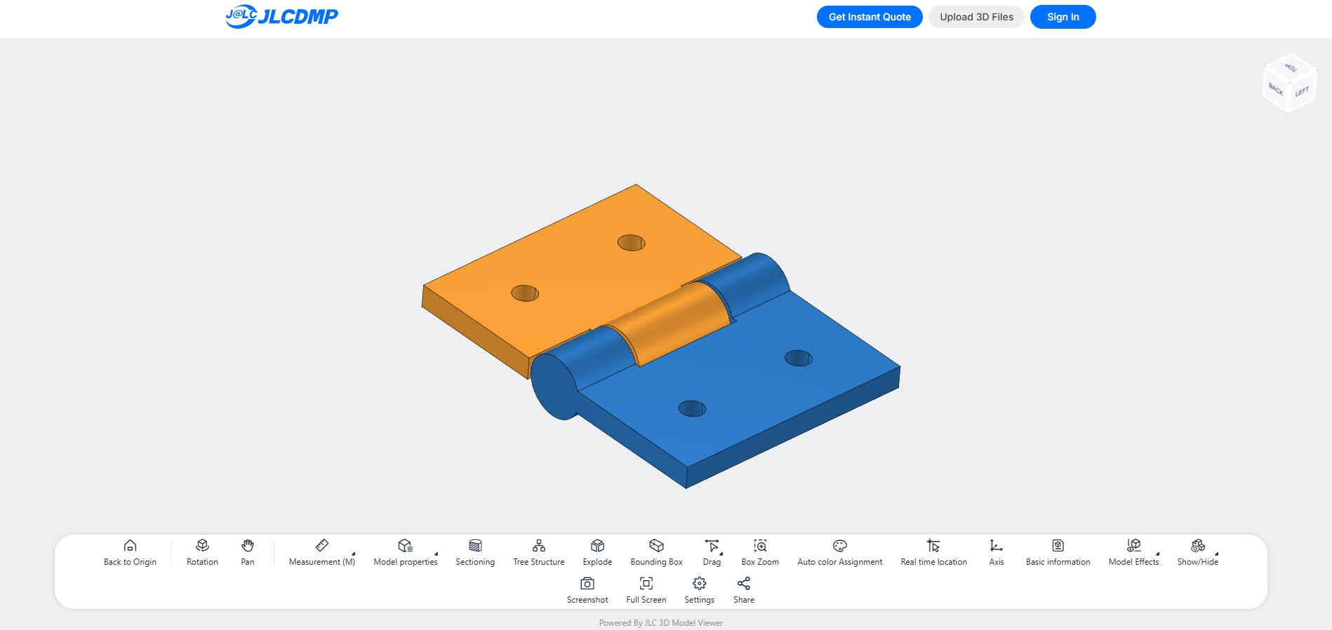
In a print-in-place hinge, a pin and surrounding sleeve are manufactured together but must remain separate after printing. The pin rotates within the sleeve without being inserted later. Chains and captive ball joints follow the same principle: the printer makes several mechanically independent elements in one job. If you have not settled on a print-in-place design yet, see JLC3DP's guide to 3D printed hinge types, materials and processes for a wider comparison before you fix the joint geometry.
Clearance is the intentional empty space between the surfaces intended to move past one another. For a concentric pin inside a sleeve, it is the separation from the pin's outer surface to the sleeve's inner surface. Without it, two seemingly distinct bodies in a CAD model can become a single physical piece after printing.
The clearance for 3D printed parts that are manufactured separately and assembled later is different: fitting and adjustment can happen after printing. For a captive hinge, the surfaces may be inaccessible. Both XY separation, measured across a layer, and Z separation, measured between stacked layers, matter. A drawing that shows daylight between the pin and sleeve in one view may conceal a touching retaining lip somewhere else. Check that every moving surface remains separate.
Why Print-in-Place Parts Fuse Together or Rattle Loose
FDM: Extruded Material Closes the Gap
In fused deposition modeling (FDM), the nozzle lays down beads of softened filament. The deposited bead has finite width, and actual deposition may occupy more space than the model's ideal boundary. A narrow gap between the hinge pin and sleeve can disappear if neighboring roads spread into it or the first layer expands beyond its intended outline.
SLA: Unwanted Curing Creates a Connection
Stereolithography (SLA) uses light to cure liquid resin. A narrow cavity that appears open in CAD can still contain resin exposed by scattered or transmitted light. If material inside the clearance partially cures, the hinge can become bonded even when the designed surfaces do not touch. In enclosed joints, access for washing away uncured resin also matters.
SLS and MJF: Heat and Trapped Powder Restrict Movement
Selective laser sintering (SLS) and Multi Jet Fusion (MJF) build parts in powder. The surrounding powder supports complex geometry, but hot material remaining inside an enclosed hinge can partly consolidate or resist removal. A gap may be present in the CAD file yet remain packed with material after production. A peer-reviewed study of MJF powder removal confirms that cleaning intricate enclosed geometries is a genuine process challenge. Its experiments concern lattices, not hinge gaps, so its numerical findings cannot establish a minimum hinge clearance. See JLC3DP's discussion of MJF tolerances for related dimensional effects.
Why Does a Printed Hinge Rattle?
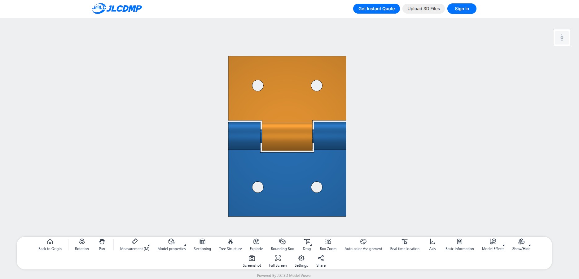
Hold one leaf still and move the other across the pin. Sideways wobble points to play between the pin and bore. Now slide the leaf along the pin. End play points to the gaps between the knuckle ends or retaining shoulders. Measure the gap that matches the symptom. If the printed hinge has more play than the model predicts, compare the printed pin and bore dimensions before changing the design.
Three Variables That Change the Printed Gap
Machine accuracy and calibration. Positioning error, extrusion settings, exposure behavior, and machine condition can shift the boundaries of a small opening. Two printers fed the same file may produce different running clearances. A printer already over-extruding small features can close a hinge gap that looked acceptable in CAD.
Material behavior. PLA is often a practical first material for FDM clearance trials. PETG may string or adhere differently; ABS can shrink noticeably as it cools. Flexible TPU may grip the other side through friction and deformation even where a rigid material rotates easily. These differences explain why a clearance proven in one material is not automatically portable to another.
Direction and geometry. XY and Z gaps are formed in different ways. For a Z-direction separation, use dimensions that correspond to whole planned layer heights so the surfaces do not inadvertently share a layer. Chamfers, retaining heads, and curved transitions can reduce the local gap below the main sketch dimension. The tightest point controls whether movement starts.
How Much Print-in-Place Hinge Clearance Is Enough?
There is no universal print-in-place hinge tolerance. The workable separation depends on printing process, material, joint shape, orientation, and machine calibration. First choose a documented baseline for the actual manufacturing process. Then check the geometry and confirm it with a representative test print.
Measurement convention: the published minimum is the gap between two facing surfaces, not a clearance to add on top of the measured gap. If a specification explicitly describes a symmetrical diameter difference, the radial clearance on each side is half that diameter difference. Do not halve an already specified local surface-to-surface gap.
JLC3DP's 3D printing design guidelines (section 5B) list minimum clearances of 0.5 mm for FDM plastic and SLA resin, and 0.6 mm for SLS and MJF nylon for simple moving features. An enclosed hinge may need more room for cleaning. Those numbers are starting baselines, not guaranteed release values for enclosed hinges. A deep sleeve, curved retaining detail, or powder pocket may require more space. Use the print-in-place clearance test to print a small sample with several gap sizes and find which gap lets the joint move freely on your printer with your chosen material.
A clearance fit intentionally leaves room for movement, unlike transition or interference fits. The fit category describes function; it does not prove printability. Different manufacturers can publish a different threshold for their own equipment. Formlabs gives a separate example: its clearance guidance for SLA parts notes that on a Form 4 with Grey Resin at a 50 µm layer height, gaps below 0.4 mm may fuse. This does not override JLC3DP's SLA guideline or establish a general rule for every resin printer. It illustrates why a number without its printer and material context can mislead.
How to Check Print-in-Place Clearance in Your Model Before You Print
A narrow gap can be invisible at normal zoom. Sectioning makes the design inspectable, while the right measurement option establishes a number. The following workflow was checked on a two-body STEP hinge. You can check the gap in your model in the free JLCDMP 3D Viewer, using the correct measurement tool. The example uses a 5.00 mm pin and a 6.20 mm concentric bore. These are model dimensions, not measurements of a print.
1Upload the Original, Correctly Scaled File
Open the viewer and upload an STL or STEP model. Confirm the expected size and units before inspecting a small joint feature. A STEP file retains precise geometry, whereas a tessellated STL may make a circular boundary harder to select accurately. If a downloaded print-in-place box STL is reduced to half size, a previously designed 0.6 mm gap becomes 0.3 mm. Recheck the scaled geometry.
2Section Through the Pin and Sleeve
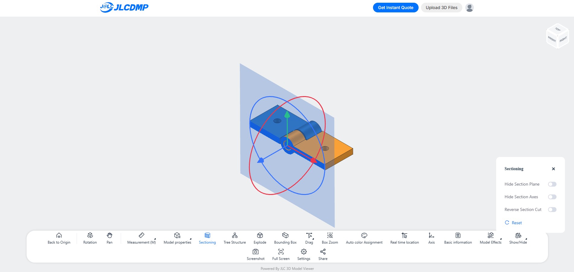
Choose Sectioning, orient the cut through the hinge barrel, and hide the section plane and axes once the pin and bore are visible. The cut shows whether the design leaves a continuous empty region around the pin. Inspect knuckle ends too.
3Measure the Two Circles and Confirm Their Centers
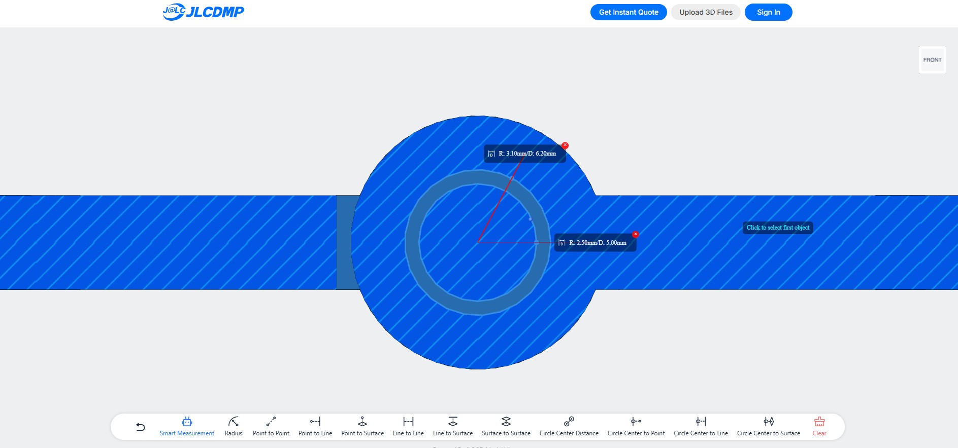
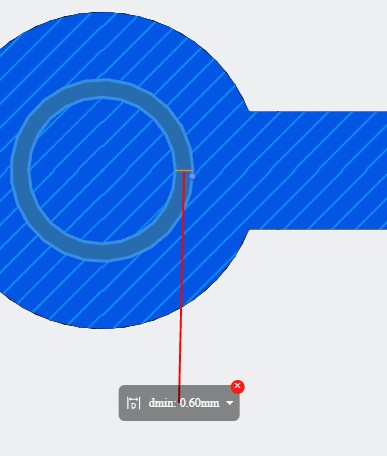
In the tested STEP model, Smart Measurement identifies the bore diameter as 6.20 mm and the pin diameter as 5.00 mm. With Circle Center Distance, selecting their original circular edges confirms that the two circles are concentric and reports a minimum edge-to-edge distance, dmin, of 0.60 mm. This is the shortest local radial gap between the concentric cylindrical surfaces, on either side of the pin. The diametral difference is 1.20 mm and must not be confused with that gap.
For a concentric pair, the same result follows from (6.20 - 5.00) / 2 = 0.60 mm. The formula requires concentric circles. If a freshly sectioned edge is not selectable, select the original geometric circular edges instead. This check uses the two original circular edges rather than the flat surface-to-surface tool, which is meant for planar faces.
4Inspect a Perpendicular Section and Axial Gaps
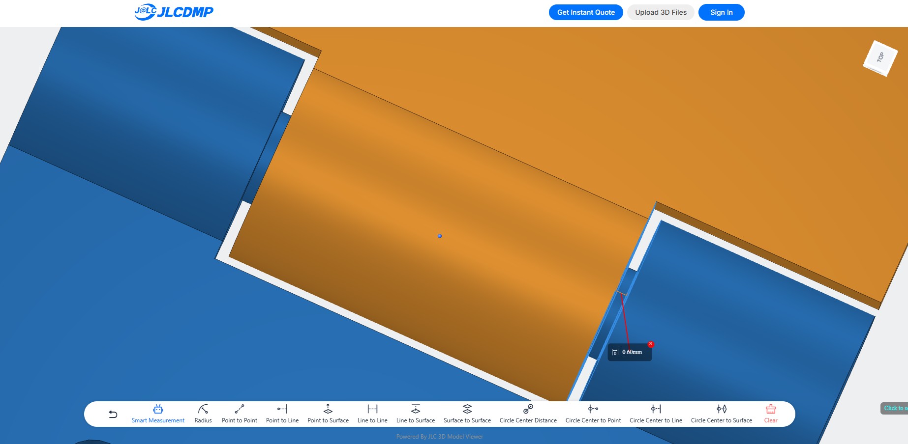
Turn the inspection toward the length of the barrel to reveal the interfaces between its three knuckles. These axial gaps are different from radial pin clearance. In our hinge, Smart Measurement on the original visible knuckle references reported a 0.60 mm axial gap. Check both ends and any retaining features.
5Compare Print-in-Place Clearance With Your Process Baseline
Record what each measurement means: local surface separation, radial clearance per side, or diametral difference. Compare the smallest relevant local gap with process guidance and a previous successful print on the intended equipment. The JLC3DP minimums refer to the open space between facing surfaces, not an extra allowance to apply twice. Trapped cavities may need more space.
A viewer checks the modeled gap, not the printed gap. Extrusion error, material shrinkage, unintended curing, and powder removal can change the physical result. This check catches missing or undersized gaps before printing.
What to Do If Your Joint Still Fails
Once you have ruled out missing clearance, adjust only the feature related to the failure. A cylindrical pin and sleeve often provide a more forgiving printed geometry than two broad, facing flat surfaces: their changing cross-section can reduce the unsupported horizontal area that an FDM layer must span. That is a design consideration, not a guarantee of support-free printing in every orientation.
A small, appropriate edge fillet can reduce a sharp stress concentration, but it must not intrude into the moving gap. For Z-direction joints, align intentional separations with your selected layer height. For a first FDM diagnostic print, a relatively rigid and familiar filament such as PLA often makes the result easier to interpret before switching to TPU or nylon. For wider guidance on orientation, overhangs, and supports, see JLC3DP's design for additive manufacturing resource.
Check Your Model Again After Adjusting Clearance
After changing a hinge, export the revised model and inspect it again rather than relying on the earlier measurement. Repeat the same section positions and compare the shortest relevant gaps. Confirm that a larger opening has not made a retaining tab too thin, shortened the bearing surface, or introduced unwanted free play. Keep the original STEP file as the stable review record. The viewer also presents a Share option with access permissions and expiry dates for collaborative inspection; verify that any generated link opens for the recipient before relying on it.
FAQ about Print-in-Place Hinge Tolerance
Q: Can a Print-in-Place Hinge Have a Gap and Still Be Fused?
Yes. A CAD gap is an empty region in the design, while a printed gap is affected by material deposition, curing, heat, and cleanup. The section check can rule out touching model faces, but it cannot predict all process effects. Compare the gap with guidance for the specific process, then print a small test if the joint is critical.
Q: Why Does a Hinge Move at First and Then Break?
The joint may have enough clearance to release but insufficient strength at the retaining lip, pin root, or thin knuckle. Forcing a sticky joint can also create a crack that becomes visible only after a few rotations. Inspect load-bearing features and contact edges, not just the open space around the pin. The failure location matters more than the initial feel.
Q: Does Scaling an STL Change Its Hinge Clearance?
Yes. Uniform scaling changes all lengths, including the narrow movement gap. A model with a 0.6 mm total surface gap scaled to 75% has a 0.45 mm total gap. Inspect dimensions after resizing a downloaded model rather than trusting the original designer's clearance note. Also verify that wall thickness and retaining details remain printable.
Q: Can a 3D Viewer Prove That a Hinge Will Rotate Freely?
No. A viewer can help identify a missing or undersized designed gap, but it does not reproduce bead spreading, cure bleed, powder removal, material friction, or long-term wear. Its measurement is a geometric preflight check. A controlled print remains the practical confirmation, especially for joints under repeated load.
Q: Should the Same Clearance Be Used for PLA, TPU, and Nylon?
Not without testing. PLA, flexible TPU, and nylon differ in shrinkage, stiffness, friction, and process behavior. A TPU sleeve may deform and grip a pin that rotates inside a rigid PLA sleeve, while powder-bed nylon requires attention to trapped powder. Start from the applicable process guidance, then test the actual material and design.
Conclusion: Print-in-Place Hinge Clearance
A print-in-place hinge depends on a gap designed into the model before printing. Too little separation can create a fused joint, while excessive play can make it rattle or lose support. A sensible print-in-place hinge clearance starts with process-specific guidance and ends with a real-world trial on the intended machine and material.
Before slicing, inspect the pin and sleeve in a sectional view, measure the closest relevant surfaces, and label the value as a total gap or per-side distance. The free 3D Viewer provides a useful geometric check, not a guarantee of printed motion.
Keep Learning
Print-in-Place Hinge Clearance: Why Parts Fuse
Key Takeaways A print-in-place hinge has mechanically separate surfaces within one printed object. The separation must exist in the model before the print starts. A narrow gap can close through extrusion, unintended resin curing, or partially fused powder. An excessive gap can reduce guidance and make a joint rattle. For simple moving features, JLC3DP's moving-part design guidelines list minimum clearances of 0.5 mm for FDM plastic and SLA resin, and 0.6 mm for SLS and MJF nylon. An enclosed hinge may......
Non-Manifold Edges in 3D Printing and Why Prints Fail
Key Takeaways Non-manifold edges are mesh edges shared by one face or by three or more faces; in a closed printable solid, every edge should join exactly two. Broken or branching layer outlines can leave a slicer unable to determine where solid material belongs. Boolean seams, overlapping bodies, deleted faces and poorly joined exports are common places to find trouble. A viewer reveals visible symptoms; mesh analysis checks connectivity, and the sliced preview checks the proposed print. Spot Mesh Err......
What Is B-rep (Boundary Representation) in CAD?
Key Takeaways B-rep (boundary representation) is the method CAD systems use to describe a 3D object by its boundaries: the faces, edges, and vertices that enclose it. It pairs topology, how those elements connect with exact mathematical surfaces, which is why B-rep models support precise measurement and manufacturing. B-rep combines two layers. Topology records face-edge-vertex connectivity; geometry stores the mathematical equations (planes, cylinders, NURBS) those elements sit on. Mesh formats carry......