Designing 3D Printed Hinges for Strength, Movement, and Durability
27 min
- What Are 3D Printed Hinges?
- Types of 3D Printed Hinges
- Advantages and Limitations of 3D Printed Hinges
- Best Materials for 3D Printed Hinges
- Industrial 3D Printing Processes for Hinges
- How Strong Are 3D Printed Hinges? Strength & Cycle Life
- How to 3D Print a Working Hinge
- Common 3D Printed Hinge Troubleshooting
- Real-World Case Studies of 3D Printed Hinges
- FAQs About 3D Printed Hinges
Yes, you can 3D print a hinge. And the better question is "which hinge are you printing?". A strip of thin polypropylene that flexes thousands of times is a hinge. So is a titanium door bracket that carries a car door through a decade of slams. Both come off a printer, and almost nothing else about them matches.
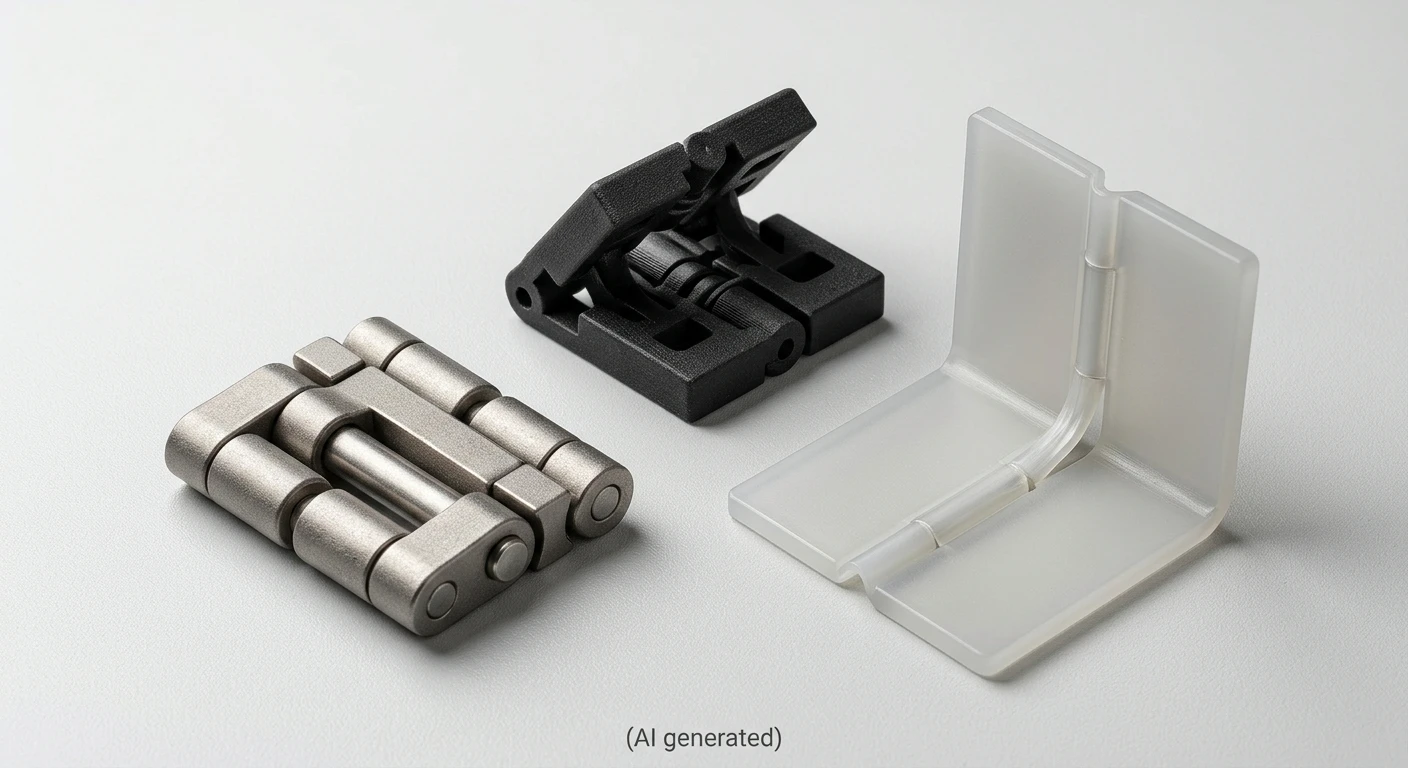
That range is what makes this topic interesting. Additive manufacturing can print a moving joint in one piece with no assembly, or it can make a single load-bearing part that a pin then runs through. Type, material, process and expected life all pull on each other, so this guide takes them in the order a design decision actually unfolds.
Key Takeaways
- Most failed 3D printed hinges fail for a mechanical reason that was baked in before printing started: the layers ran the wrong way, the material couldn't flex, or the clearance ignored what the chosen process could hold.
- Desktop FDM suits prototypes and light-duty hinges.
- Industrial processes such as MJF and SLS give more isotropic parts and reliable moving gaps.
- Metal printing earns its place when a hinge has to be strong and light at once.
- No hinge type is best in general, and the right one follows from motion, load and cycle count.
What Are 3D Printed Hinges?
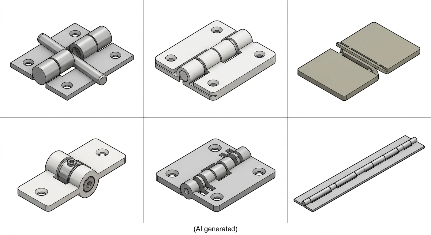
Comparison of pin, print-in-place, living, friction, detent and piano hinge mechanisms.
A 3D printed hinge is a joint manufactured through additive manufacturing that allows two connected parts to move relative to each other. Depending on the design, it can use a separate pin, a print-in-place rotating mechanism, or a flexible section that bends to create motion.
The geometry is obtained from a CAD file, so the hinge can be designed to fit the product shape.
Knuckles can be offset, a stop can be built into the barrel, a spring feature can share the same body as the leaf. Parts that would normally be three or four items on a bill of materials can become one.
Types of 3D Printed Hinges
There are two useful ways to classify the hinges. One by its manufacturing method. The other by its movement i.e. hinge mechanism. These classifications overlap, as the same hinge can fit into both groups.
Classifying hinges by construction and movement helps you understand both how a hinge is made and how it functions, making it easier to compare designs and choose one that suits your application.
-
Print-in-place
Printed together as one assembly
-
Separately printed
Individual components joined after printing
-
Living hinge
One-piece design with a flexible section
-
Pin
Rotation around an axis
-
Friction
Resistance to rotation
-
Snap-fit
Elastic engagement or retention
-
Compliant / flexure
Movement through bending
-
Ball-and-socket
Multi-directional movement
-
Detent / torque
Position holding or rotational resistance
-
Piano / continuous
Rotation along an extended axis
1By Manufacturing Method
1) Print-in-place hinge
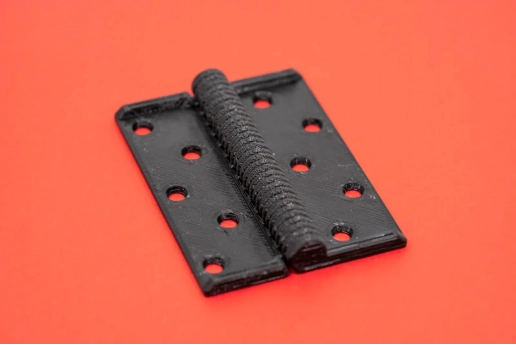
(Printables)
It is produced as one connected assembly. Its moving surfaces must have enough clearance to move freely after printing. If the gap is too small, the parts may fuse together or become difficult to separate.
For a closer look at how to prevent fused or loose joints, see our guide to print-in-place hinge clearance, including clearance measurements and design checks.
- Suitable for processes that can maintain the required gaps and remove trapped powder or resin.
- Choose this for articulated prototypes, small enclosures, and assemblies with moving parts that you want to print in one job without manual assembly. Useful when reducing part count matters more than replacing individual components.
2) Separately printed hinges
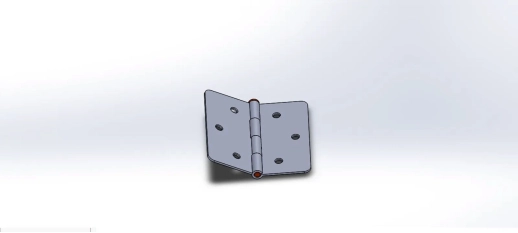
(Printables)
Individual hinge components are printed separately and joined with a pin, fastener, or other connecting feature. This approach allows you to use a metal pin, select different materials for different parts, or replace a worn component without printing the entire assembly again.
- Works across many printing processes. A separate metal pin can improve wear resistance and strength.
- Choose this for load-bearing covers, access panels, equipment doors, and functional assemblies that need a separate pin or stronger wear-resistant components. Useful when you need to replace, repair, or upgrade individual parts.
3) Monolithic flexure hinge
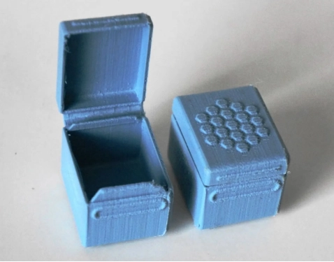
(Printables)
It works differently. A flexible section connects two rigid sections and bends to allow movement without a separate pin or bearing. A living hinge is a thin, localized form of this design. It has no separate pin or rotating bearing surfaces. Instead, a flexible section bends as the connected parts move. Usually consists of a thin web that repeatedly folds along a defined line. Its performance depends heavily on the material's flexibility and resistance to fatigue.
- Requires a material that can tolerate repeated deformation. Material choice and bend geometry strongly affect service life.
- Choose this for lightweight lids, packaging closures, and clips that repeatedly open and close through bending. Best for designs with limited loads and a flexible material that can withstand repeated flexing.
2By Hinge Mechanism
1) Pin hinge
A pin passes through aligned knuckles, allowing two parts to rotate around one fixed axis (straightforward rotation around one axis). This may be confused with the "Separately printed hinges" and the classification can be confusing. But, the difference is that the previous one describes how the hinge is manufactured, while this one describes how it moves.
- Suitable for printed knuckles with a separate metal or polymer pin.
- Choose this for doors, access panels, brackets, and other parts that need simple, controlled rotation around one fixed axis. A good choice when the hinge must support a defined load and use a replaceable pin.
2) Friction hinges
Friction between contacting surfaces creates resistance, helping the hinge hold a position instead of swinging freely.
- Suitable when the process can produce consistent contact geometry and controlled tolerances.
- Choose this for adjustable covers, display stands, and laptop-style lids that need to stay at the angle where the user leaves them. Useful when you need continuous positioning rather than fixed stopping points.
3) Detent hinges
A spring-loaded feature, bump, or recess creates preferred positions. Usually have interlocking teeth. Movement between these positions produces a noticeable click or resistance.
- Possible with carefully designed engagement features, although small details and wear need consideration.
- Typical applications include positioning covers, adjustable mounts
- Choose a detent hinge when a cover or component needs to click into specific positions.
4) Torque hinges
A friction-based or spring-assisted mechanism provides controlled resistance as the hinge moves.
- Can be printed, but consistent torque may require separate friction elements or metal components.
- Choose a torque hinge when it needs controlled resistance throughout its movement, such as an adjustable equipment lid or monitor support.
Detent and torque hinges should not be treated as identical. Detents provide preferred positions; torque hinges provide resistance to movement. An engineer choosing between them needs to know whether the design requires fixed stopping positions or continuous angle adjustment.
5) Piano / Continuous hinge
A long series of interlocking knuckles runs along an edge, with a pin passing through them. It is a continuous form of pin hinge. It is not a separate movement principle. This arrangement helps support a long lid or panel along much of its length.
- Suitable for printed sections, although long hinges need attention to straightness, alignment, and pin clearance.
- Choose this for long doors, access panels, and equipment lids that need support along most of their length. The continuous arrangement distributes the hinge connection along the edge rather than concentrating it at a few separate hinges.
6) Ball-and-socket joint
It is different from a conventional hinge. A spherical end sits inside a matching socket, allowing rotation in multiple directions rather than around one fixed axis. But it should be described as a joint rather than a standard hinge.
- It is useful for adjustable mounts and articulated assemblies.
- Choose this for camera mounts, adjustable fixtures, and articulated supports that need angular adjustment in multiple directions. Use it when a single-axis hinge would restrict the required movement.
7) Compliant hinge
It does allow relative angular movement between connected sections, but it achieves this through elastic bending rather than rotation around a pin. A living hinge is a specific type of compliant hinge, usually with a thin, flexible section.
- Best suited to materials and geometries that can withstand repeated bending without cracking or permanent deformation.
- Choose this for compact mechanisms that need smooth, low-friction movement without pins or separate bearings. Useful for small mechanisms and precision positioning, provided the flexible region can withstand the required bending cycles.
One classification detail to keep in mind! Snap-fit describes a way of joining or retaining components, not a movement mechanism by itself. A hinge can use snap-fit features to hold a pin or connect its parts, but it is still classified by its actual movement mechanism.
- Starting From $0.3 per part · No Minimum Order Quantity
- 24-Hour Lead Time · Up to $123 Welcome Coupons
Advantages and Limitations of 3D Printed Hinges
Pros
- Makes it easier to produce complex hinge shapes that would be difficult or expensive to mold or machine.
- Enables customization to fit an enclosure, combines multiple components into one assembly, and reduces weight by removing material from low-load areas.
- Speeds up prototyping, as you can adjust clearances, pin dimensions, or geometry in a CAD file without making a new mold.
Cons
- Printed hinges may have lower strength across layer interfaces.
- Polymer parts can creep under sustained loads, wear at moving contact surfaces, or change dimensions with temperature and moisture.
- Print orientation, dimensional accuracy, and surface finish affect how well the hinge fits and moves, impacting its suitability for the application.
Best Materials for 3D Printed Hinges
Material decides whether a hinge flexes, wears or breaks, and the right choice depends on the hinge type as much as on the part. For a broader comparison of printing materials, see our best 3D printing material guide. Elongation figures matter most for flexing parts, and our article on elongation at break explains how to read them.
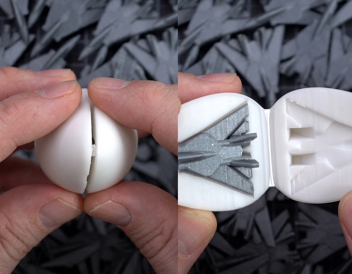
(Reddit)
The ratings below are qualitative and for hinge use specifically. Datasheet values vary by supplier and grade, so treat them as a way to rank options.
| Material | Process | Flexibility | Fatigue resistance | Interlayer bonding | Cost | Suitability rating for hinges |
|---|---|---|---|---|---|---|
| PLA | FDM | Low. Rigid and relatively brittle, with little ability to tolerate repeated bending. | Poor choice for repeatedly flexing sections. Cracks can develop under cyclic strain. | Depends on layer temperature, adhesion, and orientation. Weak Z-direction bonding can cause splitting. | Low | Low: Visual prototypes, static hinge leaves, and non-moving demonstrations. Avoid for working living hinges. |
| ABS | FDM | Moderate. More ductile than PLA, but not designed for large repeated flexing. | Depends on grade, print quality, and strain. Not a reliable living-hinge choice without testing. | Depends on thermal conditions and road-to-road adhesion. Warping can also affect part quality. | Low to medium | Moderate: Functional prototypes, housings, and light-duty hinge components. |
| ASA | FDM | Moderate. Rigid with some ductility, but not highly flexible. | Grade- and orientation-dependent. Better suited to rigid components than repeatedly bent flexures. | Depends on print settings and layer orientation, as with other FDM materials. | Medium | Moderate: Outdoor enclosures, covers, and stationary hinge components where weather resistance matters. |
| TPU | FDM | High. Elastic deformation allows it to bend and recover, depending on hardness and grade. | Potentially suitable for repeated flexing, but life depends on strain, geometry, hardness, and print quality. | Road-to-road adhesion is important. Poor bonding can cause separation during repeated bending. | Medium | High for selected flexures: Flexible joints, compliant features, and low-load living hinges. Test cycle life before production. |
| PA12-CF | FDM | Low to moderate. Carbon-fiber reinforcement increases stiffness and reduces deformation. | Not a first choice for repeatedly bending hinges because the reinforcement limits flexibility. | Depends on the polymer matrix, fiber orientation, and layer adhesion. | Medium to high | Moderate: Rigid hinge leaves, brackets, and lightweight structural components. Not suitable for thin living hinges. |
| PETG | FDM | Moderate. More ductile than PLA, but its bending behavior varies by grade. | Can work for occasional flexing, but repeated-cycle performance needs testing. | Depends on extrusion temperature, cooling, and print orientation. | Low to medium | Moderate: Light-duty hinge prototypes, clips, and pin-hinge components. Not a default choice for high-cycle living hinges. |
| PA12-HP Nylon | MJF | Moderate. Tough enough to tolerate some deformation, but it is not an elastomer. | Suitable for functional moving components, although hinge-specific cycle life needs testing. | Powder fusion avoids FDM-style bead interfaces. Directional mechanical differences can still occur. | Medium | High: Print-in-place hinges, pin-hinge components, snap features, and functional assemblies. |
| PA11-HP Nylon | MJF | Higher ductility than typical rigid PA12 grades, depending on the material specification. | A candidate for flexible clips and moving features, but repeated-bending performance must be verified. | Powder fusion rather than FDM road bonding. Check the supplier's directional properties. | Medium to high | High for selected flexible parts: Snap features, compliant components, and impact-resistant moving assemblies. |
| SLS nylon: (3021PA-F, 3301PA, 1172Pro) |
SLS | Depends on the specific nylon grade. Generally tougher than brittle standard resins. | Can suit functional moving parts, but the three grades should not be treated as interchangeable. | Powder fusion creates a consolidated part. Z-direction strength and porosity still depend on the material and process. | Medium | High for selected designs: Print-in-place assemblies, pin-hinge components, and complex functional mechanisms. |
| Standard resin (LEDO 6060, Imagine black) |
SLA | Low. Usually rigid, with limited elongation before fracture. | Poor choice for repeated bending or flexure hinges. | Photopolymer layers are cured together, but brittleness and directional properties depend on resin and curing. | Medium | Low: Detailed visual prototypes and rigid hinge geometry checks. |
| Tough resin (9600, 8001, JLC black) |
SLA | Moderate, depending on the resin formulation. | More suitable for impact and deformation than standard resin, but not automatically suitable for high-cycle flexures. | Depends on resin chemistry, layer exposure, and post-curing. | Medium to high | Moderate: Detailed functional prototypes and low-cycle mechanisms. Validate repeated movement before use. |
| Polypropylene (PP) | Injection molding | High. Its ductility allows thin sections to bend repeatedly without immediate fracture. | Well established for molded living hinges when the hinge geometry and material grade are properly selected. | Not applicable to conventional injection-molded parts. | Low at volume | High: A strong industry reference for high-cycle living hinges and packaging closures. |
| 316L stainless steel | SLM or binder jetting | Very low. Rigid and not intended to flex like a polymer living hinge. | Fatigue performance depends on surface finish, porosity, defects, build orientation, and post-processing. | Not applicable in the FDM sense. Fusion quality, porosity, and build direction affect mechanical performance. | High | High for selected rigid components: Corrosion-resistant pins, brackets, and load-bearing hinge parts. |
| Titanium TC4 | SLM | Very low. Rigid, with no practical use as a polymer-style living hinge. | Can support demanding structural applications, but fatigue must be assessed using the actual printed and finished condition. | Not applicable in the FDM sense. Defects, surface condition, and build orientation influence fatigue. | High | High for selected structural parts: Lightweight, strong hinge brackets and components where mass reduction matters. |
Industrial 3D Printing Processes for Hinges
You might choose PA12 for a pin hinge, but still need to decide between MJF and SLS.
Or you might choose a flexible material for a living hinge, but discover that the available printing process and material combination doesn't provide the fatigue life they need.
That's why, below, we’ve provided a process selection table. It takes the material choice one step further and addresses manufacturability.
| Process | Choose it when... | Suitable hinge structures | Why it fits | What to watch for |
|---|---|---|---|---|
| FDM | You need an economical prototype, a flexible polymer hinge concept, or a lightweight structural bracket. | Living-hinge prototypes, separately printed pin hinges, simple print-in-place hinges, lightweight brackets. | TPU can accommodate bending in compliant designs. Reinforced PA12-CF offers greater stiffness for brackets that do not need to flex. | Layer adhesion and print orientation affect strength. Thin hinge sections can fail along layer boundaries. Supports and dimensional variation can interfere with moving joints. |
| MJF | You need functional nylon components, complex moving assemblies, or low-volume production. | Print-in-place hinges, separately printed pin hinges, interlocking assemblies. | PA12 and PA11 offer useful toughness for functional hinge bodies. Powder-bed printing allows connected moving features without conventional support structures. | Trapped powder must be removed from moving joints. Clearance, surface texture, and dimensional variation affect movement and fit. Nylon toughness does not guarantee long fatigue life in living hinges. |
| SLS | You need complex nylon geometries, interlocking components, or moving assemblies that would be difficult to support with conventional methods. | Print-in-place hinges, separately printed pin hinges, interlocking assemblies. | Unsintered powder supports the geometry during printing, allowing complex internal features and connected components. Nylon grades can provide useful mechanical properties for functional prototypes. | Powder evacuation is essential for moving joints. Surface roughness and dimensional variation can affect joint clearance and pin-bore fit. Check the selected nylon grade's mechanical properties. |
| SLA | Fine details, small features, and smooth surfaces matter more than repeated mechanical loading. | Small pin-hinge prototypes, detailed mechanisms, visual models, low-load moving prototypes. | High resolution helps reproduce small knuckles, pin openings, and intricate geometry. Tougher resin formulations can improve impact resistance compared with standard resins. | Standard resins are generally brittle under repeated bending. Toughness does not establish fatigue resistance. Account for support removal, washing, post-curing, and resin drainage. |
| SLM | You need a metal hinge component for demanding structural applications where polymer stiffness or strength is insufficient. | Load-bearing hinge leaves, brackets, structural pin-hinge components. | Produces dense metal components with complex geometries. Titanium TC4 and 316L offer different combinations of strength, stiffness, and corrosion resistance. | Support removal, residual stress, surface finish, and build orientation affect the final part. Pin bores may need machining. Fatigue performance depends on material, defects, surface condition, and post-processing. |
| Binder jetting | You need a metal hinge component with complex geometry and can accommodate post-sintering dimensional changes. | Metal hinge bodies and smaller structural components where the final density and mechanical properties meet the application requirements. | Powder-based printing allows complex geometries without conventional support structures during the printing stage. 316L offers corrosion resistance for suitable service environments. | Debinding and sintering cause shrinkage. Final density, mechanical properties, dimensional accuracy, and bore fit must be checked. Critical pin bores may require machining. |
When to Choose an Industrial Service Over Desktop FDM
Desktop FDM is a good call for a quick prototype or a hinge nobody will stress.
An industrial service becomes the better call when tolerances are tight, when you need more than a handful of parts, when the part has to be nylon or metal, or when load and lead time matter. As said above, the isotropic behavior of MJF and SLS is the main reason.
How Strong Are 3D Printed Hinges? Strength & Cycle Life
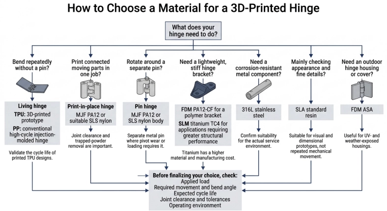
A 3D-printed hinge can handle repeated movement and mechanical loads, but its service life depends on more than the material's tensile strength. Print orientation, layer bonding, hinge geometry, and the type of movement all affect how it performs.
The weakest portion of a structure fails first and is typically between layers in FDM.
Intralayer vs. Interlayer Strength in FDM
FDM parts are built by depositing heated filament in successive layers. Each layer contains continuous or connected filament roads, while adjacent layers bond together at their interfaces. These two directions do not necessarily have the same mechanical strength.
Intralayer strength describes the strength within a deposited layer, particularly along the filament paths. Interlayer strength, also called interlaminar strength, describes the bond between adjacent layers.
Interlayer bonding is often a critical weakness in FDM parts. Usually the deposited filament must fuse with the material beneath it. If the weld is incomplete or gaps remain between layers, the interface becomes a potential crack path. A load that pulls these interfaces apart can cause delamination, even when the filament itself is relatively strong, this is known as anisotropy. Parts are generally strong along the X and Y axes (intralayer) but weaker along the Z-axis (interlayer).
This difference matters in a hinge! Because the thin flexing region experiences repeated bending. If the bending stress acts across weak layer interfaces, cracks can form and spread with each cycle.
How Print Orientation Affects Hinge Strength
Print orientation (how you position a part on the printer's build plate) determines how the filament roads and layer interfaces align with the applied load. It can therefore change where a hinge is strongest and where it is most likely to fail.
A study by Gonabadi et al. (2020) demonstrates how strongly build orientation can affect the mechanical properties of PLA produced by fused filament fabrication (FFF). In tensile tests, on-edge specimens reached 55 MPa, while upright specimens had approximately 91% lower tensile strength. The shear tests showed a similar pattern: 45° flat specimens reached 36 MPa, compared with 18 MPa for upright specimens. This represents a 50% reduction in shear strength for the tested upright specimens.
These results come from specific PLA specimens and printing conditions, so they should not be treated as universal values for every FDM printer or PLA grade. They do show why orientation matters: a hinge printed with layer interfaces positioned across its main load path may be more vulnerable to separation than one whose filament roads better follow the direction of stress.
For a working hinge, aim to orient the part so the main tensile stresses run along the deposited filament roads rather than pulling adjacent layers apart. The best orientation depends on the hinge geometry and direction of movement, so inspect the expected bending and loading directions before choosing how to place the part on the build plate.
How Material and Process Affect Hinge Durability
Material properties also influence how long a hinge can withstand repeated movement.
For example, HP reports a tensile strength of 48 MPa in both XY and Z directions for its 3D High Reusability PA12 material, measured using ASTM D638. However, its reported elongation at break differs between directions: 20% in XY and 15% in Z. This is manufacturer data for a specific MJF PA12 material, not a guarantee that every nylon powder or printed hinge has the same properties.
Living hinges provide another useful comparison. A 2019 study by Balderrama-Armendáriz et al. evaluated thermoplastic hinges made using polymer extrusion additive manufacturing. It reported the following folding endurance:
| Material tested | Folding cycles before failure |
|---|---|
| Polypropylene (PP) | 1,000,000 |
| TPU | More than 2,000,000 |
| PLA | Fewer than 1,000 |
The results show a substantial difference between the tested materials. However, they apply to the specific hinge specimens and test setup used in that study. They should not be treated as guaranteed service-life figures for every printed PP, TPU, or PLA hinge.
Design Factors That Improve Hinge Life
Material choice and print orientation are only part of the design. These factors also influence hinge durability:
- Material flexibility: A living hinge needs enough elongation to accommodate repeated bending without cracking. TPU and PP are more suitable candidates than standard PLA, but their performance depends on the grade and hinge geometry.
- Print orientation: Orient FDM parts to reduce tensile loading across weak interlayer interfaces. Check the load path through the flexing region rather than choosing orientation based only on appearance.
- Annealing: Heat treatment can change crystallinity and mechanical properties in some polymers. Its effects depend on the material and process, and it can also cause dimensional changes. Test the treated part before relying on an improvement.
- Stress concentrations: Sharp corners and abrupt thickness changes concentrate stress. Use smooth transitions and suitable radii around the flexing region and hinge connections.
- Hinge geometry: Flexure thickness, bend radius, length, and movement angle determine how much strain the hinge experiences during each cycle. Avoid forcing the hinge beyond its intended range of motion.
How to 3D Print a Working Hinge
1Choosing the Right Process
Pin, snap-fit, and living hinges are the easiest and most economical options when paired with the right filament. SLA yields high detail for small mechanisms under similar constraints, whereas SLS and MJF (using nylon) excel in load-bearing, print-in-place designs. Metal hinges require SLM or binder jetting. Since no process is universal, always match the manufacturing method to your geometry and load requirements before designing.
2Print Orientation and Layer Adhesion
Orientation determines where the weak plane sits. A pin printed lying flat has layers running along its length, so it resists bending well. Printed upright, the same pin has layer lines across its width and can snap along one. Knuckles loaded in the direction that pulls layers apart are the usual failure. Arrange the part so the main loads are carried along the layers.
3Clearance and Tolerance
There is no universal clearance. The gap that works depends on the process, material, geometry and printer, and shrinkage changes the final size. Print-in-place gaps must be large enough that moving surfaces don’t fuse, and a pin-to-hole fit has to allow for the process’s accuracy. To avoid risk, print a small test hinge and measure it first.
4Structural Design Considerations
The life of a flexing section is determined by thickness and bend radius. The geometry of the knuckles and the diameter of the pin determine the distribution of loads. Stresses are concentrated in thicker walls and ribs, generous fillets at pivot locations prevent cracking from starting. The load should be distributed over more than one knuckle.
5Post-Processing and Assembly
Remove supports, clear loose powder or resin from the gap, and clean up the contact surfaces so they move freely. Install pins, check alignment, and cycle the hinge by hand before it ships. Metal parts may need bores machined and threads tapped.
Test the hinge before committing to production
A small prototype can reveal fused gaps, loose pivots and restricted movement before you move to a larger batch. Send your CAD model to JLC3DP to explore suitable printing options for your hinge design.
Common 3D Printed Hinge Troubleshooting
| Problem | Likely cause | Practical fix |
|---|---|---|
| Parts fused together | Clearance too small for the process | Widen the gap or switch process |
| Stiff or restricted motion | Rough surfaces, residual powder or support marks | Clean the gap, sand contact faces |
| Loose pin or sloppy fit | Clearance too large or shrinkage | Resize the hole, use a printed-to-fit test |
| Cracking at the joint | Sharp corners or wrong layer direction | Add fillets, reorient the part |
| Layer separation | Loads across layers, low interlayer bonding | Reorient, change material, consider nylon |
| Loss of holding torque | Wear on friction surfaces | Add replaceable inserts, change material |
Real-World Case Studies of 3D Printed Hinges
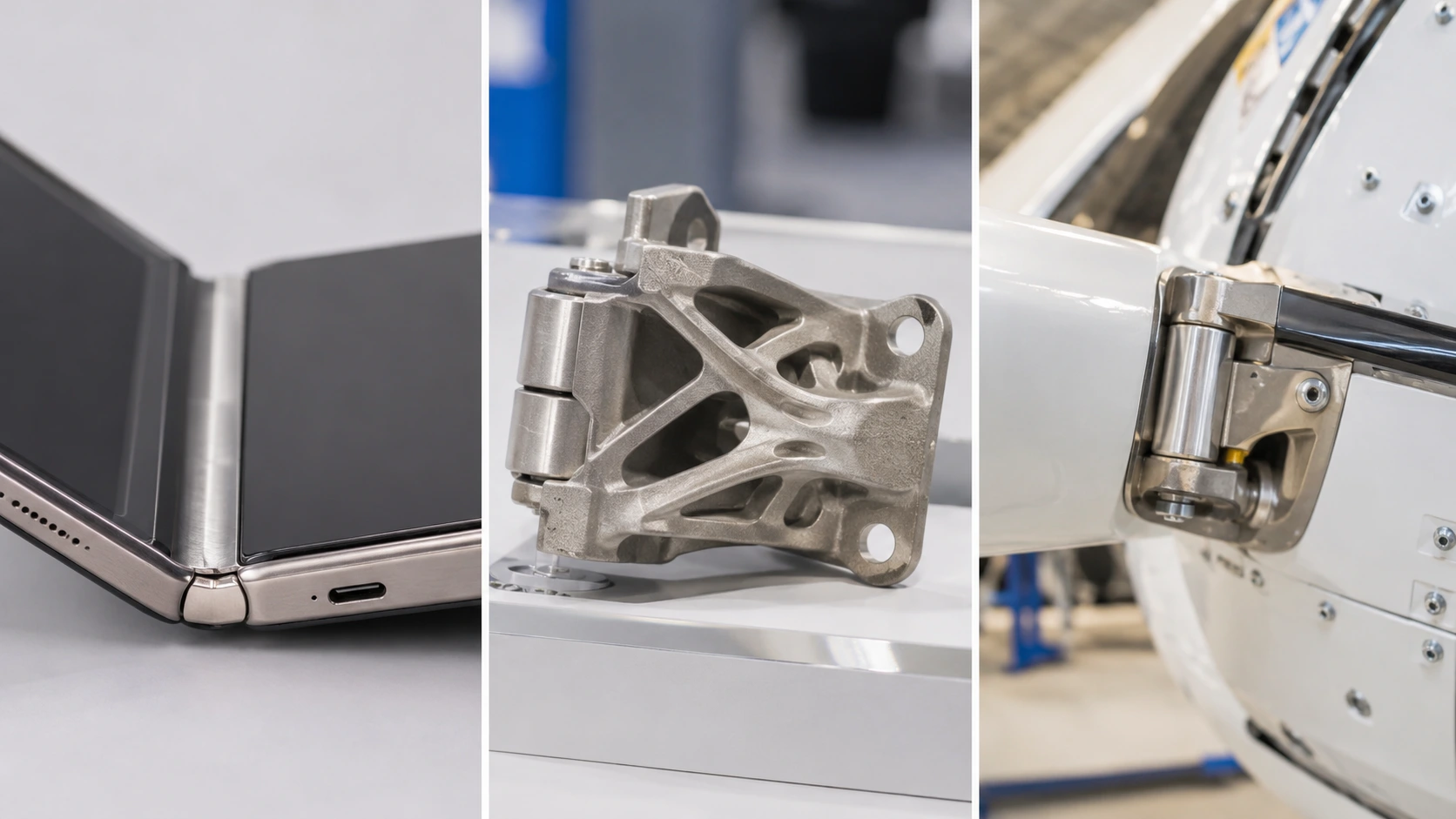
1Apple's iPhone Duo Hinge Cover and Precision Finishing
The iPhone Duo is equipped with a 3D-printed titanium hinge cover that has a micro-blasted finish. The entire hinge mechanism has over 100 parts; the printed cover is not a fully 3D-printed hinge mechanism. Apple's product announcement confirms the printed cover and titanium construction.
Another step for precision correction is also part of the manufacturing process. There is a confocal laser which scans each hinge assembly and the system can print up to 25 micro-layers of a custom photopolymer to compensate for the residual surface waviness, according to Apple hardware executive Johny Srouji. AI algorithms also match each hinge with their appropriate housing for proper alignment. TechCrunch reported Srouji's explanation.
The important point is how these processes work together. Metal additive manufacturing produces the titanium cover, while scanning and localized photopolymer deposition address surface variation and component fit. The micro-layers are a finishing or correction operation, not the method used to print the complete hinge assembly.
2BLT's Topology-Optimized Titanium Automotive Door Hinge
Bright Laser Technologies (BLT) presented at Formnext 2025 with an automotive door hinge made of titanium alloy featuring functional blades integrated into the hinge and a lightweight base plate. Industry reports indicate the additively manufactured design has a mass of about 50% less than a similar cast aluminum or cast iron design. Metal AM's report on BLT's automotive applications describes the design and its reported weight reduction.
The weight savings comes from the re-distribution of material within the component. Topology-driven design is a method of designing structures in which material is placed where it is needed to carry load and material is removed from areas that do not. These complex shapes and integrated features can be achieved using 3D printing with metals, which is not possible with casting using the same tooling and part geometry.
BLT also claims to have enhanced load paths and fatigue durability. But there are no specific fatigue-cycle results nor a detailed test protocol in the public report. The 50% weight reduction is not a "real" reduction, but a reported project comparison.
Explore more examples in our 3D printing for car accessories guide.
3QinetiQ's 3D-Printed Titanium Helicopter Hinge
A more direct example of a printed hinge reaching operational use comes from QinetiQ and Additive Manufacturing Solutions (AMS). The partners developed a titanium hinge for an air data boom mounted on a QinetiQ-owned Agusta A109S helicopter. QinetiQ designed and integrated the component, while AMS manufactured it using titanium recovered from a decommissioned aircraft.
In February 2026, the helicopter completed a flight with the printed hinge installed. This makes the project notable beyond its material choice: the component moved from design and manufacture into an actual aircraft flight test. The recycled feedstock also addresses a separate manufacturing challenge. Titanium is expensive and can be difficult to source, so recovering it from retired aircraft offers a way to reuse a valuable material. AMS reported 97% material efficiency for its recycling process. QinetiQ's project announcement provides the project details.
The flight demonstrates that the hinge was installed and used during the test. It should not be presented as proof of full service-life qualification or long-term fatigue performance, since the public announcement does not provide those results.
FAQs About 3D Printed Hinges
Q: Can you 3D print a hinge?
Yes. Hinges can be printed in place, as assembled parts, or as living hinges, in plastic or metal.
Q: Do 3D printed hinges last?
It depends on material, orientation and cycle count. Nylon and polypropylene-class materials last far longer in flexing service than PLA.
Q: What is the strongest way to 3D print a hinge?
Orient loads along the layers and use a material with good interlayer bonding, such as nylon from SLS or MJF, or metal for heavy loads.
Q: Can PLA make a living hinge?
It can for a few cycles, but PLA fatigues quickly, so flexible materials are better.
Q: What clearance should a print-in-place hinge have?
It depends on the process and material, so test a small sample and follow your provider’s guidelines.
Keep Learning
Designing 3D Printed Hinges for Strength, Movement, and Durability
Yes, you can 3D print a hinge. And the better question is "which hinge are you printing?". A strip of thin polypropylene that flexes thousands of times is a hinge. So is a titanium door bracket that carries a car door through a decade of slams. Both come off a printer, and almost nothing else about them matches. That range is what makes this topic interesting. Additive manufacturing can print a moving joint in one piece with no assembly, or it can make a single load-bearing part that a pin then runs t......
3D Printed Heat Sinks: Design, Materials & Manufacturing
Key Takeaways 3D printed heat sinks enable complex fins, lattice structures, and internal cooling channels that are difficult for traditional manufacturing. 3D printing does not improve cooling performance; simple designs are often better suited to extrusion or CNC machining. Copper provides maximum thermal conductivity; aluminum balances performance, weight, and cost, with customizable anodized colors. Choose the manufacturing process based on design complexity, precision, and production volume. Post......
3D Printing for Rapid Prototyping: Pick the Right Tech, Material & Budget
Rapid prototyping with 3D printing lets engineers turn a CAD file into a physical part in days instead of weeks. No tooling. No minimum order quantities. No waiting for a machine shop to fit your job into the schedule. Just a design file and a printed part you can hold, test, and iterate on before committing to expensive production tooling. That's the core value proposition. But additive manufacturing prototyping isn't a single process, it's a family of technologies, each suited to different prototype......
Functional 3D Printing for Real Parts: Design Rules, Materials & Uses
Functional 3D Printing for Real Parts: Design Rules, Materials & Uses Key Takeaways Functional 3D printing is used for real, load-bearing parts, not just prototypes. Design matters more than material — poor geometry or orientation causes most failures. SLS and MJF PA12 offer the most reliable performance for production-grade polymer parts. Metal 3D Printing (SLM/BJ) is essential when requirements exceed the thermal or mechanical limits of polymers. Success depends on the "Triple Threat": orientation, ......
Mass Customization Manufacturing: Benefits, Costs & 3D Printing
Key Takeaways Mass customization lets manufacturers produce unique or personalized products at near-mass-production costs. Unlike traditional manufacturing that requires expensive tooling upfront, mass customization, especially through 3D printing, skips that entirely. You get flexibility without the usual price penalty. The technology making this possible today includes parametric CAD design, 3D printing farms, and digital supply chains that can handle thousands of different configurations without re......
3D Printed Houses: the future of residential construction?
In recent years, 3D printed houses, as a new type of housing, have attracted a lot of attention. The news mentioned that this technology can complete the construction of houses in less than 24 hours, and it is more economical and environmentally friendly than traditional construction methods. What is the actual effect of 3D printed houses? This article will analyze the current status of this emerging construction technology and the problems it faces from multiple perspectives. Source: TODAY.com 1. The......