3D Printed Articulated Animals: Design & Print Guide
36 min
- What Are 3D Printed Articulated Animals?
- How Do Articulated Animal Joints Work?
- How to Design a Print-in-Place Articulated Animal
- How Much Clearance Do Articulated Animal Joints Need?
- How Manufacturing Process Changes Joint Design
- Do Not Scale Joint Clearance Proportionally
- Clearance Is Only One Part of a Functional Joint
- Recommended Design Rule for JLC3DP Articulated Animals
- How to Prepare an Articulated Animal STL
- Best Materials for Print-in-Place Articulated Animals
- Best 3D Printing Settings for Articulated Animals
- How to Print a One-Piece Articulated Animal
- Common Problems With 3D Printed Articulated Animals
- How to Improve Print-in-Place Articulated Animal Designs
- Where to Get Articulated Animal 3D Models
- Need Professional 3D Printing for Your Articulated Animal?
- FAQ about 3D Printed Articulated Animals
- Conclusion: 3D Printed Articulated Animals Design and Print Guide
Key Takeaways
Design for movement first: Define how the animal should bend or move, then design joints before building the body around them.
Critical dimensions matter: For FDM print-in-place joints, start with 0.2-0.3 mm clearance per side (0.4-0.6 mm total gap). Keep walls at 1.2-1.6 mm minimum, and 1.6-2.0 mm around stressed joints.
Never scale functional geometry proportionally: A 0.6 mm joint gap scaled to 50% becomes 0.3 mm, falling below reliable manufacturing limits. Scale visual details, but redesign critical dimensions.
Test before committing: Print a clearance ladder with multiple gap sizes (0.15-0.40 mm) to find your printer's reliable minimum before printing the full model.
Material and process affect design: PLA, PETG, and TPU each require different clearance strategies. FDM, SLA, and MJF/SLS have different minimum requirements.
What Are 3D Printed Articulated Animals?
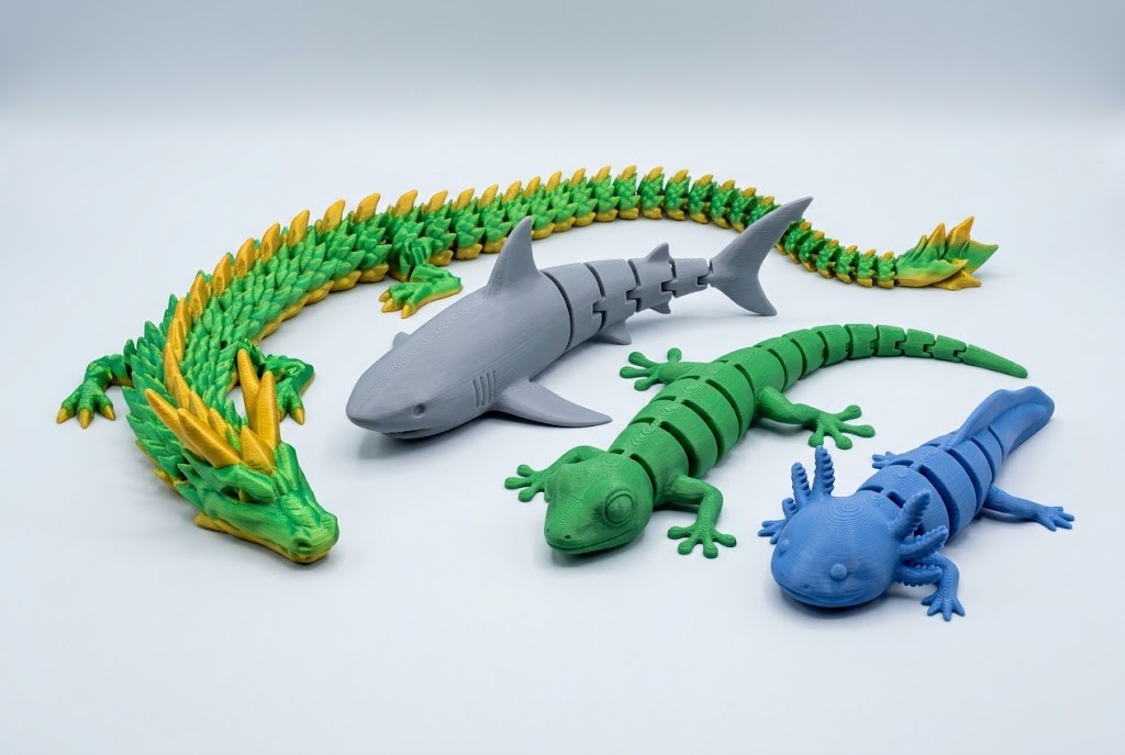
3D printed articulated animals are models made from multiple connected sections that can move relative to one another. Depending on the design, movement may come from mechanical joints, interlocking segments, flexible connections, or a combination of these structures.
Popular examples include:
- Articulated snakes and worms
- Flexible dragons
- Segmented fish
- Articulated lizards and geckos
- Dinosaurs
- Axolotls and other fantasy creatures
These models are popular because they combine decorative design with mechanical movement. A well-designed articulated animal can bend, twist, crawl, or move its tail and limbs while still being produced as a functional 3D printed object.
Articulated vs Flexi vs Print-in-Place Animals
These terms are often used interchangeably, but they do not always mean exactly the same thing.
- Articulated animal: An animal model that uses joints, hinges, interlocking components, or connected sections to create movement.
- Flexi animal: Usually describes a model with many linked segments that can bend and flex along its body. Dragons, snakes, and similar long-body designs are common examples.
- Print-in-place animal: A model designed to be printed as an assembled object. The moving components are already connected inside the STL structure, so no manual assembly is required after printing.
A model can belong to more than one category. For example, a one-piece articulated dragon printed directly from the build plate can be both an articulated animal and a print-in-place flexi animal.
How Do Articulated Animal Joints Work?
The joints are the most important part of a 3D printed articulated animal. They determine how the model moves, how strong it is, and whether the parts can be printed without fusing together.
Several joint strategies are commonly used.
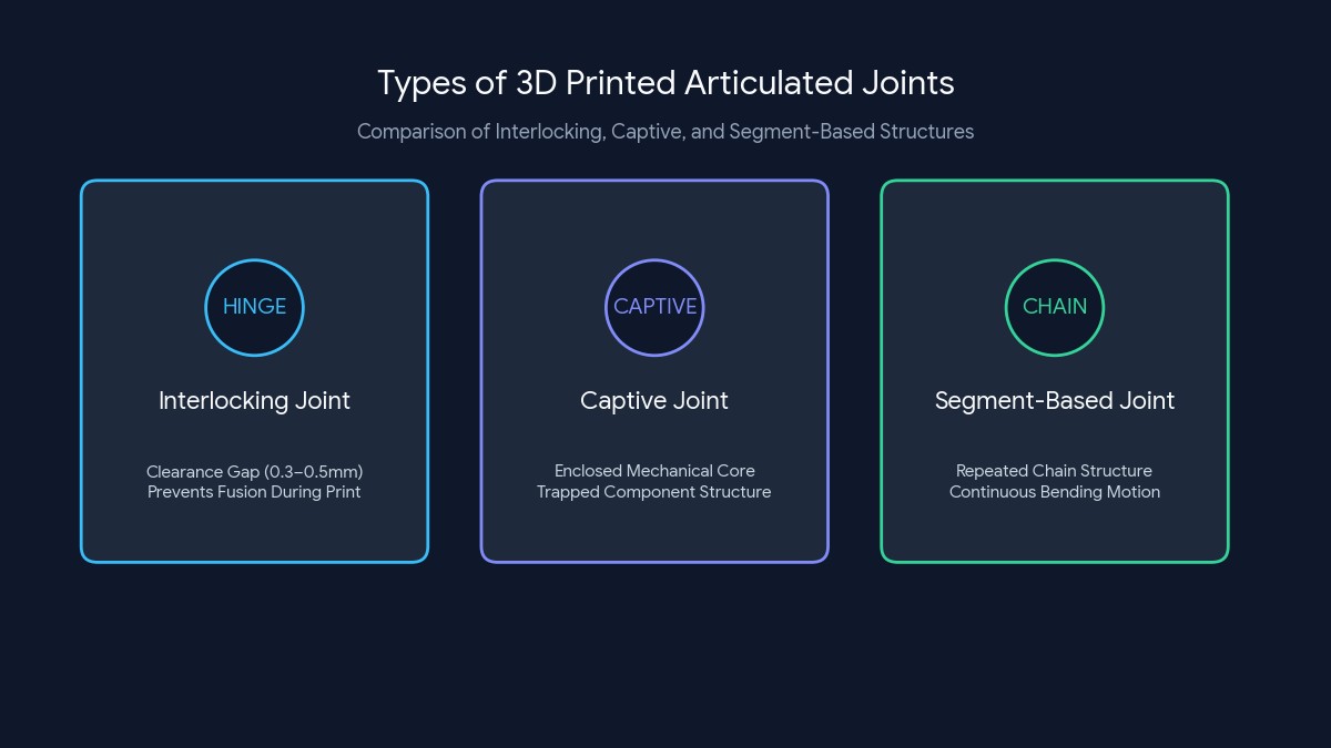
Interlocking Joints
Interlocking joints use two or more geometric features that fit together and rotate or move around a defined connection.
This approach can provide controlled movement and is useful for:
- Legs
- Heads and necks
- Tails
- Larger body segments
The joint needs enough empty space for movement, but it also needs enough material around the load-bearing area to avoid breaking.
For a typical 0.4 mm nozzle FDM setup, a useful starting point is:
- Moving-surface clearance: 0.2-0.3 mm per side
- More forgiving clearance: 0.3-0.5 mm per side
- Minimum functional wall around a lightly loaded joint: about 1.2 mm
- Recommended wall around repeatedly stressed joints: about 1.6-2.0 mm or more, depending on model size
These values are starting points rather than universal manufacturing limits. A small decorative dragon joint and a large load-bearing lizard leg should not be designed to the same dimensions.
Captive Joints
Captive joints are designed so that one part is held inside another. The parts remain mechanically connected after printing but can still rotate or move.
They are especially useful for print-in-place designs because the assembled structure is created directly during the printing process.
For captive joints, clearance must be checked around the entire moving path rather than at only one location. A joint may have a 0.3 mm gap at its widest point but still fuse if another part of the rotation path closes to nearly zero.
When checking a captive joint in CAD, inspect:
- Radial clearance around rotating features
- Axial clearance between adjacent surfaces
- Clearance at the maximum rotation angle
- Clearance near the build plate
- Clearance after accounting for first-layer expansion
Segment-Based Joints
Segment-based articulation uses many repeated sections connected in sequence.
This approach works particularly well for:
- Snakes
- Worms
- Long dragons
- Flexible tails
- Marine animals
The more segments a model contains, the smoother the overall bending motion can become. However, more joints also mean more potential points for printing problems or mechanical failure.
For repeated small segments, do not simply reduce every dimension proportionally when scaling the model down. Once the gap becomes narrower than what the printer can reproduce consistently, the joints may begin to fuse even though the CAD geometry is technically correct.
How to Design a Print-in-Place Articulated Animal
Designing a successful print-in-place articulated animal requires thinking about movement before focusing on appearance.
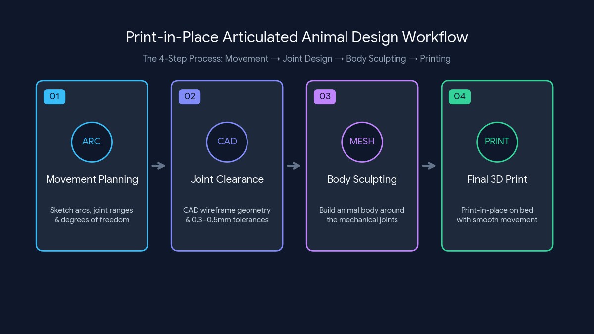
A common mistake is to finish the animal's outer shape first and then try to insert joints afterward. In many cases, the better workflow is the opposite: define the movement, design the joints, validate the joint, and then build the body around it.
Choose the Animal's Movement
Different animals require different articulation strategies.
Snakes and Worms
Snakes and worms usually benefit from many small connected segments. The main design goal is continuous bending along the body. Each individual joint may only move through a limited angle, but the combined movement of many segments creates a flexible overall shape.
Important considerations include:
- Number of segments
- Joint rotation range
- Segment length
- Body thickness
- Connection diameter
- Clearance between segments
- Strength around the connection
Smaller segments can create smoother movement, but they also reduce the available space for functional clearances. As a practical design rule, avoid shrinking a successful articulated model indefinitely. If scaling reduces a 0.4 mm total joint gap to 0.2 mm, the design may move from a reliable print to a high-risk print even though all proportions remain mathematically correct.
Fish and Marine Animals
Fish often require a different approach. Movement may be concentrated in the tail, the middle of the body, fins, or the neck or head connection. A segmented tail can create a natural swimming appearance, while a more rigid front section helps maintain the overall shape.
Because tails often become progressively thinner, check the smallest segments individually. The final tail segment may have much thinner walls and smaller clearances than the main body even when the overall design appears consistent.
Lizards
Lizards introduce more complex movement because they typically include four limbs, a flexible tail, a neck or head connection, and a relatively rigid central body. The joints must support movement without making the legs or tail too fragile.
For thin articulated legs, increasing infill alone may not solve breakage. Increasing the diameter of the connection, adding fillets at the joint transition, or increasing the number of perimeters is usually more effective than filling the entire model with additional infill.
Dinosaurs and Dragons
Dinosaurs and dragons can combine multiple articulation strategies in a single model. Common areas for articulation include segmented tails, legs, necks, heads, and wings or decorative elements.
Because these models often include thin features and complex shapes, printability should be considered throughout the design process. A useful approach is to classify features into three groups:
- Cosmetic features such as scales, horns, or spikes
- Structural features such as body walls and limbs
- Functional features such as pins, sockets, clearances, and moving surfaces
Functional dimensions should not be sacrificed simply to preserve cosmetic detail.
Start With the Joints
Before building the complete animal, create a small test version of the joint. A useful test piece should include several versions of the same joint rather than only one.
For example, test:
- 0.15 mm clearance per side
- 0.20 mm clearance per side
- 0.25 mm clearance per side
- 0.30 mm clearance per side
- 0.40 mm clearance per side
For a standard FDM printer, this type of clearance ladder can quickly reveal the smallest reliable gap for a specific printer, nozzle, material, and slicer profile.
A test piece can help evaluate:
- Whether the moving parts fuse together
- How much resistance the joint has
- Whether the connection is too loose
- Whether the surrounding material is strong enough
- How the printer reproduces small dimensions
Testing the joint separately is much faster than discovering a design problem after printing an entire articulated dragon or animal.
Build the Body Around the Joints
Once the joint design works, build the animal's shape around it. The outer body should support the mechanical structure rather than interfere with it.
For example:
- Avoid placing decorative details where they block movement.
- Maintain at least the intended clearance throughout the complete movement range.
- Add additional material around high-stress areas.
- Use fillets or smooth transitions between joints and body sections.
- Avoid sharp internal transitions around narrow connection points.
- Avoid reducing structural walls below approximately 1.2 mm on small FDM models unless the printing process has been specifically validated.
- For repeatedly flexed or loaded areas, 1.6-2.0 mm or more is often a safer starting range than a single thin wall.
The visible design and mechanical design should work together. A detailed model may look impressive in CAD software, but if decorative geometry reduces joint clearance or creates weak walls, it can reduce print reliability.
Design for One-Piece Printing
Print-in-place designs should be designed with the printing process in mind. Key considerations include:
- Whether moving parts have measurable separation
- Whether overhangs can print without excessive support
- Whether the model can rest securely on the build plate
- Whether the joints are accessible enough to move after printing
- Whether small features can be reproduced at the intended scale
Whenever possible, design the model so that the printer can produce the joints without requiring support material inside moving areas. Support material trapped between small moving parts can be difficult or impossible to remove.
For a 0.4 mm nozzle, a practical starting point for narrow functional features is:
- Absolute minimum printable line-based feature: around 0.4-0.5 mm, depending on slicer behavior
- More reliable cosmetic feature: around 0.8 mm
- More reliable functional feature: around 1.0-1.2 mm or larger
If a pin, connector, or retaining feature is smaller than the printer can reproduce consistently, increasing its size is usually more effective than trying to compensate with very slow print speeds.
How Much Clearance Do Articulated Animal Joints Need?
For a print-in-place articulated animal, clearance is one of the dimensions that determines whether the joints move freely or fuse during printing.
There is no single clearance value that guarantees success for every joint geometry. However, the clearance should not be selected arbitrarily. It should be based on the manufacturing process, material, part size, and the geometry of the moving features.
According to JLC3DP's design guidelines, the recommended minimum clearance between moving or connecting parts is:
| Manufacturing Process | Minimum Clearance Between Moving Parts |
|---|---|
| Resin (SLA) | 0.5 mm |
| Nylon (MJF) | 0.6 mm |
| Nylon (SLS) | 0.6 mm |
| Plastic (FDM) | 0.5 mm |
| Metal (SLM) | 1.0 mm |
| Metal (BJ) | 1.0 mm |
For most articulated animals produced through JLC3DP, these values should be treated as the minimum starting point for the total gap between two moving surfaces.
For example, if two parts of an articulated joint need to move independently, the distance between their opposing surfaces should meet the minimum clearance requirement for the selected process.
Design Tip
It is important not to confuse this value with clearance assigned to each side of a joint. In this article, clearance refers to the total separation between two moving parts unless otherwise stated.
JLC3DP also notes that these minimum values are intended for relatively simple structures and may not apply to every geometry. A complex articulated joint with curved contact surfaces, deep internal cavities, long moving segments, or difficult-to-remove trapped material may require additional clearance.
Recommended Starting Clearance for Articulated Animals
For print-in-place articulated animals, the following table provides a practical starting point based on JLC3DP's manufacturing limits.
| Process | JLC3DP Minimum Moving Clearance | Recommended Starting Approach for Articulated Joints |
|---|---|---|
| FDM | 0.5 mm total | Start at 0.5 mm total clearance and increase if the joint geometry is complex or difficult to separate |
| SLA | 0.5 mm total | Start at 0.5 mm and consider additional clearance for enclosed or difficult-to-clean moving features |
| MJF | 0.6 mm total | Start at 0.6 mm total clearance for moving joints |
| SLA | 0.6 mm total | Start at 0.6 mm total clearance for moving joints |
| SLM | 1.0 mm total | Generally requires larger gaps and is less suitable for very small articulated animal joints |
| BJ Metal | 1.0 mm total | Use larger clearances and evaluate the joint according to post-processing requirements |
For example, a print-in-place articulated animal designed for FDM should generally begin with at least 0.5 mm total clearance between moving parts.
If the joint contains multiple nested features, curved surfaces that approach each other closely, or internal areas where material or support removal is difficult, increasing the gap beyond the minimum may improve the reliability of the final part.
Key Principle
A joint designed exactly at the minimum may print successfully, but a slightly larger gap can provide a more reliable movement range when the geometry is complex.
A Practical Clearance Design Workflow
Instead of selecting a clearance value based only on the overall model size, use the following workflow.
1. Select the Manufacturing Process
Start by defining how the articulated animal will be manufactured. For example:
- FDM: minimum moving clearance of 0.5 mm
- SLA: minimum moving clearance of 0.5 mm
- MJF/SLS: minimum moving clearance of 0.6 mm
The process should be selected before finalizing the joint dimensions because the same articulated geometry may require different clearances for different manufacturing technologies.
2. Design Around the Minimum Manufacturing Clearance
Use the process-specific minimum clearance as the baseline total gap between moving parts. Do not reduce the clearance proportionally simply because the articulated animal is scaled down.
For example, reducing a model to 50% could reduce:
- A 0.6 mm moving clearance to 0.3 mm
- A 1.6 mm FDM wall to 0.8 mm
- A 2.0 mm structural feature to 1.0 mm
The model may still look correct visually, but its functional dimensions may no longer meet the manufacturing requirements.
3. Check the Entire Joint, Not Just One Gap
The nominal clearance may meet the minimum requirement while the joint still fails because another area becomes too close. Check:
- Pin-to-socket clearance
- Clearance between adjacent body segments
- Clearance around rotating features
- Internal trapped regions
- Minimum wall thickness around the joint
- Thin retaining features
- Clearance after scaling
The smallest local gap is often more important than the clearance value defined in the original CAD sketch.
4. Evaluate Wall Thickness and Retention Features
A joint needs sufficient clearance to move, but it also needs enough material to remain structurally stable.
According to JLC3DP's wall thickness recommendations:
| Part Size Range | Resin (SLA) | Nylon (MJF/SLS) | Plastic (FDM) |
|---|---|---|---|
| Approximately 5 × 5 mm | 0.5 mm | 1.0 mm | Not recommended for this size |
| Approximately 10 × 10 mm | 0.8 mm | 1.2 mm | Not recommended for this size |
| Approximately 50 × 50 mm | 1.0 mm | 1.5 mm | 1.6 mm |
| Approximately 100 × 100 mm | 1.5 mm | 2.0 mm | 2.0 mm |
| Approximately 200 × 200 mm | 2.0 mm | 2.0 mm | 2.5 mm |
For protrusions, positioning features, snap features, and similar functional structures, JLC3DP recommends a wall thickness of more than 1.5 mm.
This is particularly relevant to articulated animals because the necks, connectors, pins, and retention features around the joints may experience repeated movement.
A joint should therefore be designed by balancing three dimensions:
- Clearance — enough space for movement
- Wall thickness — enough material for structural strength
- Feature size — large enough to be manufactured reliably
Increasing clearance alone will not solve a joint that uses walls or retention features that are too thin.
How Manufacturing Process Changes Joint Design
FDM Articulated Animals
FDM is commonly used for large print-in-place articulated animals, but the minimum part size and wall thickness should be considered before scaling the model down.
According to JLC3DP's manufacturing limits, FDM parts have a minimum build size of 30 x 30 x 10 mm. For a roughly 50 mm-scale part, the recommended minimum wall thickness is 1.6 mm, and the minimum clearance between moving parts is 0.5 mm.
This means an articulated animal designed for FDM should not simply scale every dimension down proportionally. Once the model becomes small enough that the wall thickness, joint clearance, or retaining features fall below the recommended manufacturing limits, the joint should be redesigned rather than simply scaled.
SLA Articulated Animals
SLA can reproduce small details and thinner walls, but articulated joints still require sufficient separation between moving features.
For SLA:
- Minimum moving clearance: 0.5 mm
- Minimum wall thickness for a 5 x 5 mm part: 0.5 mm
- Minimum wall thickness for a 50 x 50 mm part: 1.0 mm
For articulated animals with enclosed joints, additional attention should be given to cleaning and post-processing. A joint that contains narrow enclosed gaps may meet the nominal clearance requirement but still be affected by uncured resin or cleaning limitations depending on the geometry.
MJF and SLS Nylon Articulated Animals
MJF and SLS are particularly suitable for complex geometries because the surrounding powder supports the part during printing.
According to JLC3DP's design guidelines:
- Minimum moving clearance: 0.6 mm
- Recommended wall thickness at approximately 50 x 50 mm: 1.5 mm
- Recommended wall thickness at approximately 100 x 100 mm: 2.0 mm
For print-in-place articulated animals with multiple moving segments, the 0.6 mm minimum clearance should be treated as a baseline between moving parts.
However, deep or enclosed joints should also be designed so that unused powder can be removed effectively.
A joint that technically has sufficient movement clearance may still cause manufacturing or post-processing problems if powder becomes trapped inside an inaccessible internal structure.
Do Not Scale Joint Clearance Proportionally
One of the most common design mistakes with articulated animals is assuming that scaling the entire STL or CAD model will preserve its functionality.
For example, imagine an original design with:
- 0.6 mm joint clearance
- 1.6 mm wall thickness
- 2.0 mm retaining feature
Scaling the entire model to 50% produces:
- 0.3 mm joint clearance
- 0.8 mm wall thickness
- 1.0 mm retaining feature
The appearance of the model may remain unchanged, but the functional geometry has changed significantly.
The reduced 0.3 mm joint clearance would fall below JLC3DP's minimum moving clearance for FDM, SLA, MJF, and SLS.
For this reason:When scaling an articulated animal down, treat the joints as functional features that may need to be redesigned independently from the outer shape.
A better approach is to scale the visual geometry while maintaining critical dimensions such as:
- Minimum moving clearance
- Wall thickness
- Connector diameter
- Retention feature thickness
- Minimum hole size where applicable
Clearance Is Only One Part of a Functional Joint
A print-in-place articulated joint can fail even when the nominal clearance meets the manufacturing requirement. Other factors include:
Joint Geometry
Curved ball joints, cylindrical hinges, and interlocking captive joints do not distribute clearance in the same way.
A nominal 0.5 mm gap in one area does not guarantee that every part of the joint maintains the same separation. Use a section view or clearance analysis in CAD to identify the smallest local gap..
Feature Size
Small pins and columns must remain large enough to survive manufacturing and repeated movement.
JLC3DP provides dimensional limits for small columns and recommends considering the relationship between column diameter and height.
For articulated joints, a very thin and tall connector may be more likely to break even if the surrounding clearance is sufficient.
Part Size
JLC3DP's wall thickness recommendations increase as the overall part becomes larger.
This is important for large articulated animals because simply maintaining the same wall thickness while significantly increasing the model size may reduce structural rigidity.
Post-Processing
The manufacturing process can also affect whether the joint remains functional after printing.
For example:
- SLA parts require cleaning and curing.
- MJF and SLS parts require powder removal.
- FDM parts may require attention to stringing or surface irregularities.
- Metal processes require significantly larger clearance and may involve additional finishing.
The joint should therefore be designed for the entire manufacturing workflow, not only for the moment the part leaves the printer.
Recommended Design Rule for JLC3DP Articulated Animals
For a practical design workflow, use the following order:
- Choose the manufacturing process.
- Set the minimum moving clearance according to the selected process.
- Check local gaps throughout the entire joint geometry.
- Verify wall thickness based on the approximate part size.
- Ensure protrusions and functional retention features have sufficient thickness.
- Check whether the model still meets these requirements after scaling.
- Evaluate post-processing accessibility for enclosed joints or cavities.
- Validate the design with the selected manufacturing process before large-scale production.
For most print-in-place articulated animals manufactured through JLC3DP, the most useful starting values are:
| Parameter | Minimum Moving Clearance | Typical Wall Thickness Consideration |
|---|---|---|
| FDM | 0.5 mm | 1.6 mm at approximately 50 mm part size |
| SLA | 0.5 mm | 1.0 mm at approximately 50 mm part size |
| MJF | 0.6 mm | 1.5 mm at approximately 50 mm part size |
| SLS | 0.6 mm | 1.5 mm at approximately 50 mm part size |
These numbers should be treated as manufacturing-oriented design baselines, rather than universal joint dimensions.
The final clearance should always account for joint geometry, part scale, wall thickness, material behavior, and post-processing requirements.
How to Prepare an Articulated Animal STL
Before printing or uploading an articulated animal for manufacturing, inspect the STL carefully.
1Check for Non-Manifold Geometry
Non-manifold geometry can create slicing errors or unexpected print results.
Common problems include:
- Open surfaces
- Intersecting shells
- Internal geometry
- Duplicate surfaces
- Invalid connections
Repairing the mesh before production can reduce the risk of unexpected printing issues.
2Check Wall Thickness
Wall thickness is particularly important for articulated animals because many designs include thin legs, small tails, narrow connectors, and small joint features. For a typical 0.4 mm nozzle FDM print, useful starting ranges are:
For a typical 0.4 mm nozzle FDM print, useful starting ranges are:
| Feature Type | Practical Starting Thickness |
|---|---|
| Light cosmetic wall | About 0.8-1.2 mm |
| General structural wall | About 1.2-1.6 mm |
| Repeatedly stressed joint area | About 1.6-2.0 mm or more |
| Thin limb or connector | Depends on length, but avoid relying on a single extrusion for a functional load path |
These are not universal material specifications. A short 1.2 mm wall may be strong enough in one area but fail immediately if the same thickness is used on a long, flexible leg.
A model may technically be printable while still containing areas that are too thin for reliable production or repeated movement.
Review the design based on the selected material and manufacturing process.
You can also refer to our guide on choosing an appropriate wall thickness for 3D printing parts.when evaluating small articulated features.
3Check Minimum Feature Size
Small decorative features and small functional features should be evaluated differently. For parts intended for JLC3DP manufacturing, it is important to distinguish between wall thickness, embossed or engraved details, holes, and load-bearing functional features.
As practical design guidelines:
- Wall thickness: Design walls to 1.2 mm or thicker to improve printability and part strength.
- Embossed and engraved details: Use a minimum feature width and depth of 1.0 mm for more reliable reproduction.
- Holes: Design holes with a diameter of at least 1.5 mm. Smaller or deeper holes may be difficult to manufacture reliably.
- Functional features: Pins, hooks, narrow connectors, and retention features should not be designed only around their visual appearance. Their dimensions should also provide sufficient strength for repeated movement and mechanical loading.
For example, a thin decorative spike may be acceptable because it carries little or no mechanical load. However, an articulated joint pin or retaining feature experiences repeated movement and stress, so simply meeting the minimum visible feature size does not guarantee reliable performance.
For print-in-place articulated animals, critical joint features should therefore be evaluated using three separate requirements: minimum printable size, wall thickness, and mechanical strength. If scaling the model down causes any of these features to fall below the recommended design limits, redesigning the joint geometry is generally more reliable than simply scaling the original model proportionally.
4Check Every Joint
Do not assume that one successful joint guarantees the entire model will work.
Inspect:
- Head joints
- Tail joints
- Leg joints
- Repeated body segments
- Small or partially hidden connections
Pay particular attention to joints with different orientations or sizes.
For each joint, check:
- Minimum clearance
- Maximum clearance
- Wall thickness around the joint
- Smallest retaining feature
- Potential interference during movement
- Distance from the build plate
5Check Build Plate Contact
The model must have enough contact with the build surface to remain stable during printing.
Poor contact can cause:
- Warping
- Partial detachment
- Shifting
- Failed first layers
For long articulated animals, also consider how the entire model is distributed across the build plate.
Best Materials for Print-in-Place Articulated Animals
Material selection affects both printability and how the final model feels during movement.
PLA
PLA is a practical choice for many rigid articulated animal designs.
It is commonly selected because it can provide:
- Good detail reproduction
- Relatively easy printing
- Clean surface appearance
- Sufficient rigidity for many decorative models
PLA is often a good starting material when developing a print-in-place articulated design because it can make it easier to evaluate the actual joint geometry.
However, PLA is relatively rigid and can be less forgiving in thin, repeatedly flexed areas. If you are comparing multiple options, our guide to choosing the right 3D printing material can help you evaluate different material properties.
PETG
PETG can be useful when additional toughness is needed.
It can offer:
- More toughnessn
- Better resistance to repeated impacts
- Greater flexibility before failure than many rigid PLA prints
However, PETG's printing behavior should be considered when designing tight clearances.
If a PLA version of a joint works with 0.2 mm clearance per side, do not assume PETG will behave identically. Test the same geometry with the intended PETG profile and increase clearance if surface buildup or stringing reduces movement.
For some PETG articulated designs, beginning around 0.25-0.35 mm per side can be a more conservative starting point.
For a more detailed breakdown, see PETG filament properties and printing settings guide.
TPU and Flexible Filaments
TPU and other flexible filaments are better suited for designs where bending is an intentional part of the model.
Potential applications include:
- Soft worms
- Flexible marine animals
- Bendable toys
- Hybrid rigid-and-flexible designs
However, a flexible material does not automatically replace mechanical articulation.
TPU can bend successfully with fewer mechanical joints, but printing very small captive joints with tight clearances may be more difficult because the material behaves differently during extrusion and movement.
Best 3D Printing Settings for Articulated Animals
The best settings depend on the printer, material, model size, and joint geometry.
Instead of copying a single profile, focus on the settings that most directly affect functional dimensions.
Layer Height
Layer height can influence surface quality and the reproduction of curved joint geometry.
For a 0.4 mm nozzle:
- 0.12-0.16 mm: useful for small joints and fine detail
- 0.16-0.20 mm: suitable for many general articulated animals
- 0.24 mm or higher: more appropriate for larger models with generous clearances
If the model contains a narrow curved joint, reducing layer height may improve the surface finish and movement. However, it should not be used as a substitute for adequate clearance.
Nozzle Size
The nozzle should match the scale of the design.
A smaller nozzle may be useful for fine details and compact joints, while a larger nozzle may be more efficient for larger models with thicker features.
The important question is whether the selected nozzle can accurately reproduce:
- The intended clearance
- The smallest functional feature
- The wall thickness
- The retaining geometry
If a joint has a 0.25 mm gap but is printed with a 0.6 mm nozzle, the design should be reconsidered rather than relying on slicer settings to reproduce geometry below the practical resolution.
Print Speed
Print speed can affect dimensional consistency.
Very high speeds may reduce accuracy on small details, particularly around:
- Joint openings
- Narrow gaps
- Small overhangs
- Repeated segments
For articulated designs, consistent geometry is often more valuable than simply reducing printing time.
A useful strategy is to reduce speed selectively for:
- - Outer walls
- - Small perimeters
- - Joint features
- - Bridges and overhangs
There is no single correct speed because acceleration, extrusion system, cooling, and printer mechanics also affect the final result.
Wall Count and Infill
For moving models, wall structure can be more important than simply increasing infill.
With a 0.4 mm nozzle, starting with 3-4 perimeters can provide approximately 1.2-1.6 mm of shell structure, depending on the actual line width.
Pay attention to areas that experience mechanical stress, including:
- Joint housings
- Thin legs
- Tail connections
- Narrow body segments
Additional wall strength may improve durability without unnecessarily increasing material use throughout the entire model.
First-Layer Calibration
The first layer is especially important for print-in-place articulated animals.
If the first layer spreads outward too much, it can reduce the available space between moving components.
This effect, often called elephant foot, can cause joints near the build plate to fuse together.
If a joint has 0.4 mm total clearance but first-layer expansion consumes 0.15-0.20 mm on both sides, the effective gap can become dramatically smaller.
Possible solutions include:
- Improving Z-offset and first-layer calibration
- Using elephant-foot compensation where available/li>
- Raising critical moving features slightly above the build plate
- Adding chamfers near the first-layer edge
- Orienting the model so the tightest joint is not directly affected by first-layer expansion
Careful first-layer calibration can help maintain the intended geometry.
How to Print a One-Piece Articulated Animal
Once the design and settings are ready, use a structured workflow.
-
Choose a Tested or Verified Model
If you are using an existing STL, check whether it has been successfully printed at the intended scale. Do not assume that a model proven at 100% scale will work at 50%.
-
Review the Joint Geometry
Inspect the joints and confirm that scaling or editing has not unintentionally reduced the clearance.
For FDM print-in-place designs, verify: Clearance per side;Total gap;Smallest wall;Smallest functional feature;Potential interference during movement
-
Select the Material
Choose the material based on the desired balance between rigidity, toughness, and flexibility. If possible, test the joint using the same material planned for the final print.
-
Check Model Orientation
Orient the model to improve build plate stability and reduce unnecessary supports. For print-in-place designs, avoid placing support material where it could interfere with moving parts.
-
Preview the Slice
Review the sliced model carefully. Check small gaps, joint layers, thin walls, overhangs, and build plate contact.
Zoom into the smallest joint. If the slicer closes a gap that exists in the STL, the problem may be caused by the combination of nozzle size, line width, wall generation, or model scale.
-
Print the Model
Monitor the early stages of the print to ensure good adhesion and stable first-layer performance.
-
Allow the Model to Cool
Removing or flexing a model before it has cooled sufficiently can damage small features.
-
Carefully Free the Joints
Once the model is ready, gently move the articulated sections. Do not force a fused joint aggressively, as this may break the surrounding material. Start with small controlled movements to determine whether the joint is fully fused, partially fused, correctly articulated, or too loose.
-
Test the Full Range of Movement
Check whether the joints move smoothly, any section is too loose, thin parts flex excessively, and movement is blocked by nearby geometry.
Common Problems With 3D Printed Articulated Animals
The Joints Are Fused
Possible causes include:
- Clearance below the printer's reliable capability
- Excess material spreading into the gap/li>
- Poor dimensional accuracy
- - Excessive first-layer deformation
- Support material entering the joint area
- Model scaling that reduced a previously functional gap
The Joints Are Too Loose
A joint may move but still feel unstable. This can result from excessive clearance, material shrinkage, joint geometry that provides insufficient retention, or wear caused by repeated movement.
The solution may involve adjusting the retention geometry rather than simply making the entire joint tighter.
For example, a captive joint may need a larger retaining lip, a deeper socket, a longer contact surface, or a larger ball or pivot diameter.
The Animal Breaks During Movement
Breakage often occurs in high-stress areas. Common causes include thin walls, sharp transitions, small connection points, insufficient material around the joint, and layer orientation that places the load across weak layer interfaces.
Consider increasing local thickness from approximately 1.0 mm to 1.6 mm or more, increasing the diameter of narrow connectors, adding fillets between the joint and body, increasing wall count around the stressed area, and changing the orientation so the main load is not concentrated across layer boundaries.
The Animal Does Not Move Smoothly
A model may technically be articulated but still feel stiff or uneven. Possible causes include rough joint surfaces, inconsistent clearance, partial fusion, printing artifacts, and nearby body geometry blocking movement.
Check whether the resistance comes from the joint itself or from another part of the animal. A useful diagnostic method is to print only several representative segments. If the isolated joint moves correctly but the complete animal does not, the problem may be interference from the surrounding body geometry.
First-Layer Elephant Foot Fuses the Joints
This is a common issue when moving features are close to the build plate. If the first layer spreads outward, it can close the gap between articulated components.
Possible improvements include improving first-layer calibration, adjusting the model orientation, using elephant-foot compensation, adding a small chamfer to the lower edge, raising critical moving geometry away from the first-layer contact zone, and increasing clearance specifically near the build plate if the joint design allows it.
Do not automatically increase clearance throughout the entire model if only the first few layers are causing fusion.
How to Improve Print-in-Place Articulated Animal Designs
Test the Joint Before the Full Animal
A small test print can save significant time and material.
Instead of printing an entire articulated dragon to test a new joint, print several representative segments first.
A particularly useful test is a clearance ladder containing multiple versions of the same joint.
This allows you to identify the best range for a specific printer and material.
Evaluate movement, strength, clearance, surface quality, retention, and resistance to repeated movement. Then update the design before committing to the full model.
Increase the Model Size During Development
Very small models can hide design problems. During early development, testing at a larger scale can make it easier to understand how the joint works. However, do not assume that the final smaller model can simply be scaled down proportionally.
When reducing size, check critical dimensions individually: Is the joint gap still large enough? Is the wall still thick enough? Is the smallest connector still printable? Can the selected nozzle reproduce the geometry?
Once critical dimensions fall below the practical manufacturing range, redesigning the small model is more reliable than continuing to scale it.
Design for the Printer, Not Just the Screen
A CAD model can look mechanically perfect while still being difficult to manufacture. Always consider minimum feature size, wall thickness, joint clearance, material behavior, layer-based construction, and build orientation.
A useful rule is: Decorative geometry can scale proportionally. Functional geometry often cannot. For example, if a dragon is reduced to 50% scale, scales and cosmetic details can usually shrink with the model. A 0.6 mm joint gap, however, may need to remain close to its original value instead of becoming 0.3 mm.
The best articulated animal designs combine visual creativity with realistic manufacturing requirements.
Where to Get Articulated Animal 3D Models
Articulated animal models are available through a variety of online 3D model communities and marketplaces. Before using an STL, consider whether you need a free or commercial model, a model licensed for personal use, permission for commercial production, a model that has already been tested as print-in-place, or a custom design for a specific project.
You can also create a custom articulated animal from scratch if you need a unique shape, movement style, size, or joint structure. When downloading any model, always review the license and verify that the intended use is permitted.
Need Professional 3D Printing for Your Articulated Animal?
If you already have an articulated animal STL, the next step is to make sure the design is suitable for the selected manufacturing process. Before production, review joint clearance, wall thickness, minimum functional feature size, material selection, model scale, print orientation, and overall manufacturability.
For custom articulated animals, a professional 3D printing service can also help evaluate whether the model's geometry and material requirements are appropriate for the intended production method. A small joint test or prototype is often the most efficient way to validate the design before producing a larger batch.
FAQ about 3D Printed Articulated Animals
Q: What are 3D printed articulated animals?
3D printed articulated animals are models made from connected sections or mechanical joints that allow parts of the animal to move. They can include snakes, dragons, fish, lizards, dinosaurs, and other segmented or jointed designs.
Q: What is a print-in-place articulated animal?
A print-in-place articulated animal is designed to be printed as a single assembled piece. Its moving sections are already connected, so manual assembly is generally unnecessary after printing.
Q: How much clearance do 3D printed articulated joints need?
For a typical FDM printer using a 0.4 mm nozzle, 0.2-0.3 mm clearance per side is a practical starting point for many print-in-place articulated joints. If the printer is less precisely calibrated, the joint is large, or the material produces more surface buildup, 0.3-0.5 mm per side may provide more reliable movement. The best approach is to print a small clearance test using the same printer, nozzle, material, and settings planned for the final model.
Q: How do articulated animal joints work?
Articulated animal joints use mechanical geometry such as interlocking features, captive connections, or repeated segments. Clearance between moving surfaces allows the parts to move without fusing together during printing, while the surrounding walls and retaining features keep the parts mechanically connected.
Q: Why are small articulated animals harder to print?
Small models have smaller gaps, thinner walls, and tighter mechanical features. Minor dimensional variations therefore have a larger effect on whether the joints move correctly. A model scaled to 50% may also reduce a previously reliable 0.6 mm joint gap to only 0.3 mm, which can significantly increase the risk of fusion.
Q: What wall thickness should I use for an articulated animal?
For a typical 0.4 mm nozzle FDM print, approximately 1.2-1.6 mm is a useful starting range for general structural walls. Areas around repeatedly stressed joints, thin legs, or narrow connections may benefit from 1.6-2.0 mm or more, depending on the model size, geometry, and material.
Q: Is PLA good for articulated animals?
PLA can be suitable for many articulated animal models because it can produce detailed, rigid parts and is relatively easy to print. It is often a good starting material for testing print-in-place joint geometry. However, the best material depends on the required flexibility, durability, and intended use.
Q: What should I test before printing the full articulated animal?
Test the joint first. A small joint prototype should evaluate clearance, movement, strength, retention, wall thickness, minimum feature size, and dimensional accuracy. A clearance ladder with several gap sizes can reveal the most reliable starting value for the specific printer and material.
Conclusion: 3D Printed Articulated Animals Design and Print Guide
The best 3D printed articulated animals are designed around movement, not just appearance. Start by defining how the animal should bend or move, develop and test the joint geometry, build the body around the mechanism, and then optimize the model for the selected 3D printing process.
For 3D articulated animals, especially small print-in-place articulated animals, success depends heavily on measurable functional dimensions rather than general descriptions such as "sufficient clearance" or "thicker walls."
As a practical starting point for a typical 0.4 mm nozzle FDM printer:
- Start with 0.2-0.3 mm clearance per side for many print-in-place joints.
- Increase toward 0.3-0.5 mm per side when greater manufacturing tolerance is needed.
- Keep general structural walls around 1.2-1.6 mm as a starting range.
- Consider 1.6-2.0 mm or more around repeatedly stressed joints.
- Avoid relying on extremely small functional features; 1.0-1.2 mm or larger is generally easier to reproduce reliably with a 0.4 mm nozzle.
- Print a representative joint test before committing to the full model.
Whether you are creating a segmented dragon, a flexible 3D printed animal, or a custom articulated creature, testing the mechanical structure early is one of the most effective ways to improve print success and achieve smoother movement in the final model.
Popular Articles
Keep Learning
3D Printed Articulated Animals: Design & Print Guide
Key Takeaways Design for movement first: Define how the animal should bend or move, then design joints before building the body around them. Critical dimensions matter: For FDM print-in-place joints, start with 0.2-0.3 mm clearance per side (0.4-0.6 mm total gap). Keep walls at 1.2-1.6 mm minimum, and 1.6-2.0 mm around stressed joints. Never scale functional geometry proportionally: A 0.6 mm joint gap scaled to 50% becomes 0.3 mm, falling below reliable manufacturing limits. Scale visual details, but ......
3D Printing vs CNC Service: How to Choose the Right Manufacturing Method
3D printing and CNC (Computer Numerical Control) service are two popular manufacturing methods that have gained widespread attention in recent years. 3D printing, also known as additive manufacturing, involves building 3D objects layer by layer from a digital model, while CNC service, also known as subtractive manufacturing, involves cutting away material from a solid block to create a desired shape. Both methods offer unique capabilities and advantages, and understanding their key characteristics is ......
Micro 3D Printing Explained: Technologies, Materials and Applications
Introduction Standard 3D printing builds parts you can hold in your hand. Micro Printing — and more precisely Micro 3D printing builds parts you need a magnifying glass to see, and sometimes a microscope. A microneedle array for drug delivery. A microfluidic chip with channels thinner than a human hair. A miniature optical lens with surface accuracy measured in microns. These aren't just smaller versions of parts you'd make on a standard FDM printer. They're a different category of manufacturing entir......
Future of 3D Printing 2026: Trends, Technologies & Applications
What Is the Future of 3D Printing? The future of 3D printing is defined by a structural transition from prototyping-centric workflows to production-integrated manufacturing systems. Rather than replacing conventional processes such as CNC machining or injection molding, additive manufacturing is increasingly positioned as a complementary production method for geometrically complex, low-to-medium volume, and highly customized components. This transition is being driven by concurrent improvements in pro......
PolyJet Alternatives: Compare Full Color 3D Printing Technologies
What Is PolyJet 3D Printing? PolyJet, commercialized by companies like Stratasys, is one of the most widely recognized material jetting technologies for high-resolution, multi-material 3D printing. PolyJet usually enters the conversation when a project demands a level of detail that standard FDM or SLS just can't touch (Here’s a comparison of FDM vs SLS vs SLA if you want to look into that). Unlike other additive processes that extrude a bead of plastic or melt a bed of powder, PolyJet operates more l......
MJF TPU vs FDM TPU: Best 3D TPU Printing Method in 2026
Do you struggle with poor results from FDM TPU printing—like visible layer lines and inconsistent strength? Or are you worried that using MJF technology for TPU parts might be too expensive when you only need a few initial samples? These problems may simply come from choosing the wrong 3D TPU printing method. Take it easy, guys. Now it is the time we break them down. This 2026 3d TPU guide will help you know the facts. So, you can pick the best choice for your flexible 3D TPU projects. 1. What Makes T......