SLS vs SLM 3D Printing: Differences, Cost, Materials & Applications
15 min
- SLS vs SLM: What Is the Difference?
- SLS vs SLM at a Glance
- What Is SLS 3D Printing?
- What Is SLM 3D Printing?
- SLS vs SLM: Key Differences
- 1. Materials and Fusion Process
- 2. SLS vs SLM Strength and Mechanical Performance
- 3. SLS vs SLM Accuracy and Tolerances
- 4. Support Structures and Design Freedom
- 5. SLS vs SLM Surface Finish
- 6. SLS vs SLM Heat Resistance
- SLS vs SLM Applications
- SLS vs SLM Cost
- SLS vs SLM: Which Process Fits Your Part?
- When SLS or SLM May Not Be the Right Choice
- SLS vs SLM vs DMLS vs LPBF
- Why Use JLC3DP for SLS and SLM 3D Printing?
- FAQ about SLS vs SLM 3D Printing
SLS vs SLM 3D printing is often treated as a head-to-head contest, but the two processes exist for different material classes. SLS, or selective laser sintering, is mainly used to produce polymer parts. SLM, or selective laser melting, manufactures metal parts by fully melting metal powder layer by layer.
For most engineering applications, the choice between SLS and SLM comes down to material requirements, mechanical performance, geometry, support structures, post-processing, lead time, and cost. This article explains how each process works, how they differ, and which questions to ask before selecting one.
Key Takeaways
- SLS (Selective Laser Sintering) is most commonly used to produce polymer parts from powder, while SLM (Selective Laser Melting) is commonly used for metal powder processing.
- SLS generally offers greater freedom for complex unsupported geometries because surrounding powder supports the part during printing.
- SLM can produce high-density metal components with strong mechanical and thermal performance, but typically requires support structures and more extensive post-processing.
- The right process depends on the material, mechanical requirements, geometry, dimensional requirements, heat resistance, production volume, and budget of the part.
- JLC3DP provides industrial SLS and SLM 3D printing with multiple material options, online quoting, engineering review, and production support.
SLS vs SLM: What Is the Difference?
The main difference between SLS and SLM is the material and powder-fusion process used to manufacture the part.
SLS uses a laser to selectively sinter polymer powder layer by layer, making it particularly suitable for functional prototypes, housings, brackets, ducts, and other complex polymer components.
SLM uses a laser to selectively melt metal powder layer by layer. It is commonly used for metal prototypes, end-use components, tooling, and parts that require high strength, stiffness, heat resistance, or complex internal structures.
In simple terms:
SLS is commonly used for polymer powder parts, while SLM is commonly used for metal powder parts.
However, the choice between SLS and SLM should not be based on material alone. Part geometry, mechanical performance, thermal requirements, dimensional requirements, production volume, and cost also need to be considered.
SLS vs SLM at a Glance
The table below summarizes the most important differences at a glance. The rest of the article adds the engineering detail behind each row.
| Factor | SLS | SLM |
|---|---|---|
| Typical material | Polymer powder, mainly nylon | Metal powder |
| Fusion mechanism | Sinters polymer particles until they fuse | Fully melts metal powder |
| Support structures | Usually none; surrounding powder supports the part | Commonly required |
| Typical density | Good, slightly porous surface | High, near fully dense metal |
| Heat resistance | Depends on polymer grade | High, metal-dependent |
| Post-processing | Bead blasting, dyeing, tumbling | Support removal, heat treatment, machining, polishing |
| Relative cost | Generally lower | Generally higher |
| JLC3DP typical tolerance | ±0.3mm (within 100mm), ±0.4% (above 100mm) | ±0.3mm (within 100mm), ±0.4% (above 100mm) |
Note that these are general tendencies, not fixed rules. Two parts in the same process can behave differently depending on material, geometry, and orientation.
What Is SLS 3D Printing?
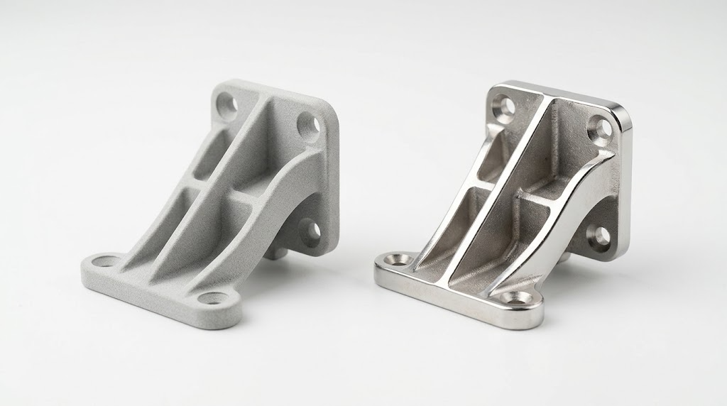
Selective Laser Sintering (SLS) is a powder-bed fusion process commonly used to manufacture polymer parts.
A thin layer of polymer powder is deposited across the build area. A laser selectively heats the powder according to the cross-section of the part. The build platform then moves incrementally, another powder layer is deposited, and the process repeats until the part is complete.
After printing, the parts are removed from the surrounding powder and cleaned.
Why Is SLS Suitable for Complex Parts?
One of the main advantages of SLS is that the surrounding powder provides support during the build.
This means many geometries can be produced without dedicated support structures, including:
- Complex channels
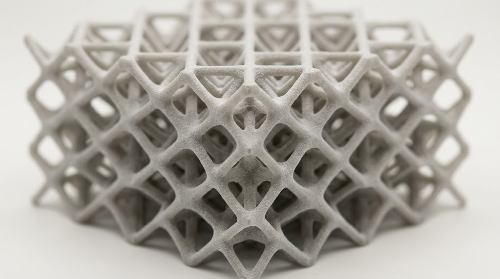
- Lattice structures
- Hinges and moving features
- Internal cavities
- Thin walls
- Interlocking components
- Organic or irregular geometries
This can simplify both design and post-processing compared with powder-bed processes that require extensive support structures.
You can read more on the JLC3DP SLS 3D printing page.
Common SLS Materials
SLS is commonly associated with engineering thermoplastics such as:
- PA12
- PA11
- Glass-filled nylon (e.g., JLC3DP 3201 PA-F)
- Other reinforced or application-specific polymer powders (e.g., JLC3DP 3301PA, 3401GB, 1172 Pro Nylon)
Material selection should be based on the required combination of strength, toughness, stiffness, temperature resistance, dimensional stability, and environmental resistance.
What Is SLM 3D Printing?
Selective Laser Melting (SLM) is a metal powder-bed fusion process that uses a laser to selectively melt metal powder layer by layer.
The laser energy melts the powder in the defined areas, creating a metallurgically bonded metal structure. The process is repeated until the complete part is built.
SLM is commonly used when conventional manufacturing methods have difficulty producing complex metal geometries or when a part requires a combination of mechanical performance and geometric complexity.
For the current service scope, see JLC3DP SLM 3D printing.
Common SLM Materials
Depending on the available equipment and process parameters, SLM can be used with materials such as:
- Stainless steel (e.g., JLC3DP 316L)
- Aluminum alloys
- Titanium alloys (e.g., JLC3DP TC4)
- Tool steels
- Other metal alloys
For example, stainless steel can be suitable for corrosion-resistant components, while titanium alloys are often considered when high strength-to-weight ratio and temperature performance are important.
The appropriate material should always be selected according to the actual application and verified material data.
SLS vs SLM: Key Differences
1. Materials and Fusion Process
The most fundamental difference between SLS and SLM is the material system.
SLS commonly processes polymer powders. The laser selectively sinters the powder to form the part.
SLM processes metal powders and uses sufficient laser energy to melt the powder and form a consolidated metal structure.
Because the materials behave differently under thermal processing, SLS and SLM also have different requirements for process control, thermal management, support structures, and post-processing.
2. SLS vs SLM Strength and Mechanical Performance
The mechanical performance of SLS and SLM parts depends heavily on material selection and processing conditions.
SLS Mechanical Performance
SLS polymer parts can provide good mechanical performance for functional prototypes and many production applications.
Their properties depend on factors such as:
- Polymer grade
- Powder condition
- Build orientation
- Wall thickness
- Geometry
- Process parameters
- Post-processing
SLS is often suitable when a part requires a balance of strength, toughness, low weight, and geometric complexity.
SLM Mechanical Performance
SLM can produce high-density metal components with mechanical properties suitable for demanding applications when the material and process are properly controlled.
However, performance can be affected by:
- Build orientation
- Laser parameters
- Powder characteristics
- Thermal history
- Residual stress
- Heat treatment
- Post-processing
Therefore, published material properties should be treated as material- and process-specific data, rather than universal values for every SLM part.
3. SLS vs SLM Accuracy and Tolerances
Neither SLS nor SLM has one universal tolerance that applies to every part.
Actual dimensional accuracy depends on:
- Material
- Machine
- Part size
- Geometry
- Wall thickness
- Build orientation
- Thermal behavior
- Process parameters
- Post-processing
SLS can experience dimensional variation due to thermal contraction and polymer behavior.
SLM introduces additional challenges because metal melting and solidification can generate thermal gradients, residual stress, and deformation.
For precision-critical features, additional machining may be required after SLM printing.
JLC3DP Design Guidelines
| Guideline | SLS | SLM |
|---|---|---|
| Typical tolerance | ±0.3mm (within 100mm), ±0.4% (above 100mm) | ±0.3mm (within 100mm), ±0.4% (above 100mm) |
| Recommended wall thickness | 1.0 mm | 1.5 mm |
| Assembly clearance | 0.2-0.4 mm | 0.5 mm |
| Moving or connecting clearance | 0.6 mm | 1.0 mm |
| Minimum Pin Diameter | 2 mm | 2 mm |
| Minimum hole | 1.5 mm | 1.5 mm |
These are JLC3DP's published design guidelines and should not be treated as universal limits for every machine or supplier. For further reading, see the guides to 3D printing tolerances and 3D metal printing design rules.
Design Tip
For both processes, avoid designing directly around a generic '3D printing tolerance.' Instead, use the service provider's design guidelines for the specific machine, material, and manufacturing process.
4. Support Structures and Design Freedom
Support requirements are one of the most noticeable differences between SLS and SLM.
SLS
SLS generally does not require conventional support structures for most geometries because the surrounding powder supports the part.
This can make SLS particularly useful for:
- Internal channels
- Hollow structures
- Lattice designs
- Complex assemblies
- Interlocking parts
However, unsupported does not mean unconstrained. Powder removal, minimum wall thickness, trapped powder, thermal distortion, and feature size still need to be considered.
SLM
SLM commonly requires support structures.
They can help:
- Anchor the part to the build plate
- Manage heat transfer
- Reduce deformation
- Stabilize overhangs
- Control distortion caused by thermal gradients
Support design is therefore an important part of metal additive manufacturing.
5. SLS vs SLM Surface Finish
SLS and SLM both produce surfaces that typically require more finishing than conventional machining.
SLS Surface Finish
SLS parts usually have a characteristic powder-textured surface.
Common finishing methods include:
- Powder removal
- Bead blasting
- Tumbling
- Dyeing
- Surface smoothing
SLM Surface Finish
SLM parts may have a relatively rough as-printed surface, particularly on downward-facing or unsupported surfaces.
Common post-processing methods include:
- Support removal
- Sanding or blasting
- CNC machining
- Grinding
- Polishing
- Heat treatment
The required finishing process depends on the appearance, dimensional, and functional requirements of the final component.
6. SLS vs SLM Heat Resistance
Heat resistance is another important selection factor.
SLS polymer parts can provide useful temperature performance, but the actual operating temperature depends on the specific polymer grade and application conditions. SLM metal parts generally provide significantly higher temperature capability than polymer SLS parts, although the actual temperature limit depends on the metal alloy, heat treatment, loading conditions, and operating environment. For high-temperature applications, material selection should therefore be based on the actual operating temperature and mechanical load, rather than simply choosing SLM because it is a metal process.
SLS vs SLM Applications
The best process depends on what the part needs to do.
SLS Typical Applications
- Functional plastic prototypes
- Lightweight components
- Complex internal geometries
- Low-volume plastic parts
- Housings, ducts, brackets
- Lattice structures
SLM Typical Applications
- High-strength metal components
- High-temperature parts
- Complex metal geometries
- Load-bearing structures
- Hollowed-out parts
- Functional structural parts with complex shapes
These are general application patterns rather than strict process limitations. The final choice should be based on the material and engineering requirements of the specific component.
SLS vs SLM Cost
SLS and SLM have different cost structures. SLS is generally less expensive for polymer parts because polymer powders and the associated processing environment are typically less demanding than metal powder-bed fusion.
SLM usually costs more because of:
- Metal powder cost
- Laser power and energy requirements
- Inert gas requirements
- Longer processing times for some geometries
- Support generation and removal
- Heat treatment
- Machining or other post-processing
- More complex process control
JLC3DP's current online service pages list starting prices from $1.00 for SLS and from $8.00 for SLM. These are starting prices rather than direct like-for-like production costs; the final quotation depends on material, geometry, quantity, and other manufacturing requirements.However, printing cost alone should not determine the manufacturing process. A more expensive SLM process may be appropriate if the component requires metal strength, high temperature resistance, or complex metal geometry that cannot be produced efficiently using conventional methods.
For a fair comparison, evaluate the complete manufacturing cost, including: Printing + material + post-processing + machining + tooling + assembly
SLS vs SLM: Which Process Fits Your Part?
Instead of asking which process is generally better, start with the requirements of the part.
A Simple Selection Flow
Step 1: Choose the material
- Need polymer → SLS may be suitable.
- Need metal → SLM may be suitable.
Step 2: Check mechanical requirements
Consider:
- Tensile strength
- Toughness
- Stiffness
- Fatigue performance
- Wear resistance
- Weight
Step 3: Check thermal requirements
Consider:
- Operating temperature
- Heat cycling
- Thermal expansion
- Heat transfer requirements
Step 4: Evaluate geometry
Check:
- Overhangs
- Internal channels
- Wall thickness
- Lattice structures
- Minimum feature size
- Powder removal
- Support requirements
Step 5: Consider post-processing
Determine whether the part requires:
- Heat treatment
- Machining
- Surface finishing
- Support removal
- Dimensional finishing
Step 6: Compare total cost
Consider the complete manufacturing process rather than the printing price alone.
When SLS or SLM May Not Be the Right Choice
SLS and SLM are powerful additive manufacturing technologies, but they are not appropriate for every application.
Consider FDM/FFF when:
- The component is relatively simple.
- Lower-cost prototyping is the priority.
- Material requirements can be met by common thermoplastics.
- Extremely high surface quality is not required.
Consider SLA when:
- Fine details are critical.
- Smooth surface finish is important.
- The component is primarily a visual or presentation prototype.
Consider CNC machining when:
- Very tight dimensional tolerances are required.
- The geometry is relatively easy to machine.
- Surface finish is a major requirement.
- Material removal is economically practical.
Consider injection molding when:
- Production volume is high.
- A stable production geometry has been established.
- Tooling investment can be justified.
The right manufacturing process is ultimately determined by the balance between performance, geometry, volume, lead time, and total cost.
SLS vs SLM vs DMLS vs LPBF
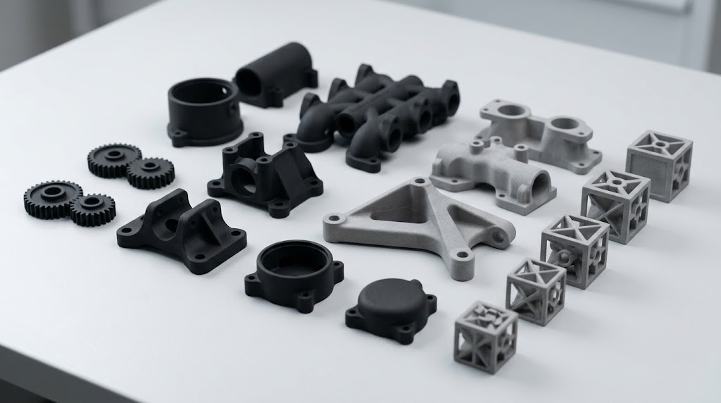
These terms are often used together in discussions about powder-bed fusion, but they are not always interchangeable.
SLS
Selective Laser Sintering is commonly associated with polymer powder processing.
SLM
Selective Laser Melting is commonly associated with metal powder processing and emphasizes the melting of metal powder.
DMLS
Direct Metal Laser Sintering is a term widely used for metal additive manufacturing. In practice, DMLS and SLM processes can have substantial technical overlap, although terminology varies by manufacturer and industry.
LPBF
Laser Powder Bed Fusion is a broader technical term describing additive manufacturing processes that use a laser to selectively process powder in a powder bed.
Therefore:
LPBF is often used as the broader process category, while SLM and DMLS are commonly used terms for specific approaches or commercial implementations of metal laser powder-bed fusion.
Terminology can vary between equipment manufacturers, standards, and engineering communities, so the actual machine, material, and process parameters matter more than the label alone.
Why Use JLC3DP for SLS and SLM 3D Printing?
For engineering teams, choosing the manufacturing service is as important as choosing the printing technology.JLC3DP provides industrial 3D printing services for both polymer and metal applications, helping engineers move from digital designs to functional parts without investing in their own additive manufacturing equipment.
Industrial 3D Printing
JLC3DP supports industrial applications where material performance, dimensional consistency, and production efficiency matter.
Available technologies include SLS and SLM, along with other industrial 3D printing processes for different application requirements.
Multiple Material Options
Material selection can be matched to requirements such as:
- Strength
- Toughness
- Weight
- Heat resistance
- Corrosion resistance
- Wear resistance
- Application environment
Fast Production
For prototypes and low-volume components, additive manufacturing can significantly reduce the need for tooling.
JLC3DP combines online ordering with production capabilities to help shorten the path from CAD design to manufactured parts.
Cost-Effective for Prototypes and Low-Volume Parts
SLS and SLM can be useful when tooling would add unnecessary cost or lead time.
By producing parts directly from digital models, engineers can manufacture small quantities without committing to conventional tooling.
Engineering Support
For complex components, manufacturing success depends on more than simply uploading a CAD file.
Design considerations such as:
- Wall thickness
- Overhangs
- Support structures
- Build orientation
- Dimensional requirements
- Powder removal
- Post-processing
should be evaluated before production.
JLC3DP's engineering-oriented workflow helps customers select suitable processes and materials based on their part requirements.
FAQ about SLS vs SLM 3D Printing
Q: Is SLS or SLM stronger?
It depends on the material and application. SLM produces metal parts and can provide high mechanical performance, while SLS produces polymer parts that can provide good strength and toughness for many functional applications.
The material grade, process parameters, build orientation, and post-processing all affect final performance.
Q: Is SLS cheaper than SLM?
SLS is generally less expensive than SLM because polymer powder processing is typically less demanding than metal powder-bed fusion.
However, the actual cost depends on part size, material, quantity, geometry, build time, and post-processing.
Q: Is SLS better for prototypes?
SLS can be highly suitable for functional polymer prototypes, particularly when complex geometry, moving features, or low-volume production is required.
However, SLA, FDM/FFF, CNC machining, or other processes may be more appropriate depending on the prototype's requirements.
Q: Which is better for complex geometries, SLS or SLM?
Both can manufacture complex geometries, but they handle complexity differently.
SLS can simplify complex polymer geometries because surrounding powder provides support.
SLM can produce highly complex metal geometries, but support structures, thermal gradients, residual stress, and powder removal need to be considered during design.
Q: Is SLS or SLM more accurate?
Neither process has a single universal accuracy value.
Actual dimensional accuracy depends on the machine, material, geometry, build orientation, process parameters, and post-processing.
For precision-critical parts, always follow the manufacturer's process-specific design guidelines.
Conclusion: SLS vs SLM 3D Printing
SLS and SLM serve different manufacturing needs.
Choose SLS when you need complex polymer parts, functional prototypes, lightweight components, or cost-effective low-volume production.
Consider SLM when you need complex metal components with demanding mechanical or thermal requirements.
The most appropriate process depends on more than the printing technology itself. Material, geometry, strength, temperature, tolerances, production volume, post-processing, lead time, and total cost should all be considered before manufacturing.For engineers who need industrial 3D printed parts without investing in additive manufacturing equipment, JLC3DP provides SLS and SLM production options with online quoting, material selection, engineering support, and global delivery.
Popular Articles
Keep Learning
SLS vs SLM 3D Printing: Differences, Cost, Materials & Applications
SLS vs SLM 3D printing is often treated as a head-to-head contest, but the two processes exist for different material classes. SLS, or selective laser sintering, is mainly used to produce polymer parts. SLM, or selective laser melting, manufactures metal parts by fully melting metal powder layer by layer. For most engineering applications, the choice between SLS and SLM comes down to material requirements, mechanical performance, geometry, support structures, post-processing, lead time, and cost. This......
The Limits of 3D Printing: Comparison with Traditional Manufacturing
3D printing technology provides new solutions for the manufacturing industry in rapid prototyping, customized production and manufacturing complex geometric structures. So can 3D printing replace traditional manufacturing? Compared with traditional manufacturing processes, 3D printing still has some obvious limitations in terms of scale speed, material selection, cost efficiency, size and accuracy. This article explores the main limitations of 3D printing from several key perspectives and makes a deta......
3D Printed Articulated Animals: Design & Print Guide
Key Takeaways Design for movement first: Define how the animal should bend or move, then design joints before building the body around them. Critical dimensions matter: For FDM print-in-place joints, start with 0.2-0.3 mm clearance per side (0.4-0.6 mm total gap). Keep walls at 1.2-1.6 mm minimum, and 1.6-2.0 mm around stressed joints. Never scale functional geometry proportionally: A 0.6 mm joint gap scaled to 50% becomes 0.3 mm, falling below reliable manufacturing limits. Scale visual details, but ......
3D Printing vs CNC Service: How to Choose the Right Manufacturing Method
3D printing and CNC (Computer Numerical Control) service are two popular manufacturing methods that have gained widespread attention in recent years. 3D printing, also known as additive manufacturing, involves building 3D objects layer by layer from a digital model, while CNC service, also known as subtractive manufacturing, involves cutting away material from a solid block to create a desired shape. Both methods offer unique capabilities and advantages, and understanding their key characteristics is ......
Micro 3D Printing Explained: Technologies, Materials and Applications
Introduction Standard 3D printing builds parts you can hold in your hand. Micro Printing — and more precisely Micro 3D printing builds parts you need a magnifying glass to see, and sometimes a microscope. A microneedle array for drug delivery. A microfluidic chip with channels thinner than a human hair. A miniature optical lens with surface accuracy measured in microns. These aren't just smaller versions of parts you'd make on a standard FDM printer. They're a different category of manufacturing entir......
Future of 3D Printing 2026: Trends, Technologies & Applications
What Is the Future of 3D Printing? The future of 3D printing is defined by a structural transition from prototyping-centric workflows to production-integrated manufacturing systems. Rather than replacing conventional processes such as CNC machining or injection molding, additive manufacturing is increasingly positioned as a complementary production method for geometrically complex, low-to-medium volume, and highly customized components. This transition is being driven by concurrent improvements in pro......