MJF vs FDM: Key Differences, Cost, and How to Choose the Right 3D Printing Process
21 min
- Introduction
- Quick Answer
- MJF vs FDM at a Glance
- What Is MJF 3D Printing?
- What Is FDM 3D Printing?
- Strength and Mechanical Properties: MJF vs FDM
- Accuracy, Resolution, and Surface Finish: MJF vs FDM
- Materials and Material Properties: MJF vs FDM
- Cost and Production Volume: MJF vs FDM
- Applications and Use Cases
- MJF vs FDM: Which 3D Printing Technology Should You Choose?
- FAQ about MJF vs FDM
Introduction
HP Multi Jet Fusion powder bed on the left, FDM extrusion — the same bracket in both processes. The FDM part is a structure with locally varying density and strength — a skin filled with tessellated rigid structures that build high strength with low weight and material usage. The MJF prototype is closer to full density, less anisotropic and more uniform in structure than FDM, and has a powdery finish.
MJF fuses nylon powder using selectively applied agents and infrared heat. FDM builds parts by depositing thermoplastic strands. Choose MJF for intricate nylon parts, multidirectional loading and batches that benefit from powder-bed packing. Choose FDM for simple prototypes, large parts, and applications requiring ASA, ABS or flexible filament. This comparison uses JLC3DP service specifications for materials it supplies; manufacturer test data is identified separately. Published mechanical figures describe standardized specimens, while finished-part performance also reflects geometry, orientation and processing.
Part geometry, production quantity and loading direction determine which process is suitable: when the geometry gets more complex, the quantity climbs from one to fifty, and the part has to carry load in more than one direction.
Here we compare the two in terms of strength and directional uniformity (isotropy), accuracy and finish, materials, cost per part, and fit to application.
The numbers used here come from HP and Stratasys datasheets, and from JLC3DP's published design guidelines, with test conditions stated.
Quick Answer
Choose FDM for a single simple prototype, large build envelopes or an application requiring ABS or UV-resistant ASA. Choose MJF for detailed nylon components, unsupported internal geometry and batches of compact parts. MJF PA12 provides more consistent directional properties than typical FDM builds. Neither process wins every quantity: compare live JLC3DP quotations for the same CAD model before placing a production order.
The datasheets show why. HP PA12 offers 48 MPa tensile strength in all axes, while Stratasys ABS-M30 drops from 32 to 28 MPa and loses about 70% of its elongation capacity in the direction of build. ULTEM 9085 printed on edge reaches 77.1 MPa and a 172.9 °C heat deflection temperature at 1.82 MPa, against 95 °C for MJF PA12.
MJF vs FDM at a Glance
| Factor | MJF | FDM |
|---|---|---|
| Printing process | Powder bed, fusing and detailing agents, infrared fusion | Heated nozzle extrudes filament layer by layer |
| Material options | PA12, PA11, PAC nylons (JLC3DP) | ABS, ASA, PLA, PA12-CF, PEBA, TPU (JLC3DP) |
| Mechanical strength | 48 MPa tensile, PA12 (HP) | 28.8 MPa, JLC3DP ABS; ULTEM not offered by JLC3DP |
| Anisotropy and layer adhesion | Low anisotropy | Orientation-sensitive; see strength section |
| Dimensional accuracy | ±0.3 mm or ±0.4% (JLC3DP) | ±0.3 mm to 100 mm, ±0.4% above (JLC3DP) |
| Surface finish | Fine, matte, granular | Visible layer lines and roads |
| Minimum feature and wall | 0.5 mm emboss or engrave; 1.0 mm wall | 0.8 mm emboss or engrave; 1.6 to 2.5 mm wall by part size |
| Part size | 370 × 276 × 360 mm (PA12) | 580 × 480 × 480 mm (ABS) |
| Speed and scalability | Many parts nested in one build | One part path at a time; best for one-offs |
| Material waste | About 20% powder refreshed per build | Supports, purge and failed prints |
| Cost per part | Falls as the build fills | Flat; lowest for a single simple part |
Sources: HP HR PA 12 datasheet, Stratasys datasheets, JLC3DP design guidelines. Various test setups prevent direct comparison.
Compare JLC3DP MJF and FDM Quotes | Upload one CAD file to compare available materials, prices and quoted production dates: compare JLC3DP MJF and FDM quotes.
What Is MJF 3D Printing?
How Multi Jet Fusion Works
A recoater roller spreads a thin layer of nylon powder over the print area. Printheads jet a fusing agent where the part slice requires it, and a detailing agent at the edges, and infrared lamps then pass over the bed and fuse the treated area. The unfused powder around the part acts as support, so overhangs and nested geometry need no dedicated support structures.
Powder support has limits. Hollow parts need escape holes, and JLC3DP specifies a minimum of 2.5 mm so trapped powder can be removed without struggle.
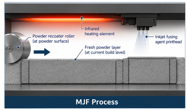
Process cross-section for MJF: recoater, fusing and detailing agent printheads, infrared lamp, fused part and surrounding powder.
MJF Materials
JLC3DP prints MJF in PA12-HP, PA11-HP and PAC-HP nylon. PA11 trades some strength for ductility: HP lists 54 MPa tensile strength and 40% elongation at break in XY. Check the current MJF-compatible materials page before specifying a grade.
Key Advantages of MJF
Loose powder supports complex overhangs and internal structures without printed scaffolding. Multiple parts can occupy the build volume in three dimensions, making MJF attractive for compact batch production. Its relatively uniform directional performance also simplifies the placement of load-bearing features. HP specifies an 80% powder reusability ratio for its HR PA12 system: a representative powder blend can contain 80% recovered powder and 20% fresh material. This is a refresh ratio, not a claim that 20% of every build is discarded.
Limitations of MJF
MJF is limited to compatible powder materials and generally produces a matte, granular surface. Closed cavities require powder escape access; unsupported assumptions about powder removal can make an otherwise printable part unusable. Industrial equipment and powder handling make service production the practical route for occasional orders.
What Is FDM 3D Printing?
How Fused Deposition Modeling Works
A drive gear pushes filament through a heated nozzle, and the printer deposits continuous strands of polymer in each layer, before Z stepping up to the next slice. The slicer sets wall strand-count, infill type/density, lay direction, and support need. Even at 100% infill the part is a bundle of bonded threads, not a uniform solid. JLC3DP's introduction to FDM covers the basics.
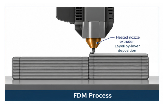
FDM bracket above, part-built, showing layering direction, layer interfaces and nozzle extrusion of the continuous build.
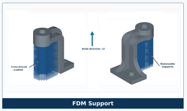
Areas which overhang require a platform and scaffold to be printed to support them. This can be printed to break off cleanly, or printed in water soluble secondary material for higher quality results.
Common FDM Materials
JLC3DP offers ABS, ASA, PLA, PA12-CF, TPU and other listed FDM grades. Choose PLA for visual and fit-check prototypes, ABS for general indoor functional parts, and ASA for outdoor housings exposed to sunlight. JLC3DP reports ABS tensile strength of 28.8 MPa under ISO 527 and 98°C heat deflection under ISO 75 at 1.8 MPa. Its ASA page reports 97.8°C heat deflection and 6.7% in-plane elongation at break. Flexible TPU suits compliant features; PA12-CF is a choice where higher in-plane stiffness is needed.
Key Advantages of FDM
FDM offers low CAPEX for a basic purchased system, the widest choice of materials and colors, and the largest build volumes. JLC3DP lists ABS parts up to 580 × 480 × 480 mm, about 57% longer than the 370 mm MJF limit.
Limitations of FDM
Basic desktop FDM has low equipment cost and is economical for simple prototype work. Industrial FDM capable of controlled high-temperature production costs substantially more to purchase and operate, so its economics are different. In either case, interlayer bonds, support scars and warping constrain functional geometry. Orient tensile loads along deposited strands wherever possible.
Strength and Mechanical Properties: MJF vs FDM
Tensile Strength and Impact Resistance
For materials supplied by JLC3DP, use the service data first. JLC3DP reports ABS tensile strength of 28.8 MPa (ISO 527), elongation at break of 3.8%, and notched impact strength of 16.4 kJ/m² (listed as ISO 179). Its ASA data reports in-plane elongation at break of 6.7% and Charpy impact strength of 10.3 kJ/m². The ASA tensile entry is printed as "43.8 ± 0.8 (%)", an apparent unit error; the figure is not treated as verified MPa pending correction. For MJF PA12, HP reports 48 MPa tensile strength in XY and Z. The current Stratasys ULTEM 9085 manufacturer sheet identifies ultimate strength separately from yield; for natural material printed with an F900 T16A tip it lists 77.1 MPa (XZ) and 59.0 MPa (ZX) ultimate strength, with 45.2 and 38.2 MPa at 0.2% offset yield. Its HDT at 1.82 MPa is 172.9°C for the natural T16 material. ULTEM is a third-party process example, not a JLC3DP FDM ordering option. Tests use different specimen and process conditions, so the numbers are material benchmarks rather than identical-part results.
| Property | MJF PA12 | MJF PA11 | FDM ABS-M30 | FDM ULTEM 9085 |
|---|---|---|---|---|
| Tensile, in-plane (MPa) | 48 | 54 | 32 | 69 |
| Tensile, Z or upright (MPa) | 48 | 54 | 28 | 42 |
| Elongation, in-plane / Z | 20% / 15% | 40% / 25% | 7% / 2% | not listed |
| HDT at 1.82 MPa | 95 °C | not listed | 82 °C | 172.9 °C |
Sources: HP HR PA 12 and PA 11 datasheets; Stratasys ABS-M30 and ULTEM 9085 datasheets (ULTEM figures from the 2016 sheet; later sheets list about 170 °C HDT).
JLC3DP ABS reports 28.8 MPa tensile strength. MJF PA12's published 48 MPa is substantially higher; the former comparison to third-party ASA data understated this difference.
Layer Adhesion and Directional Strength
FDM strands bond less effectively across layer boundaries than along their deposited paths. This makes upright clips, cantilevers and thin tensile tabs especially vulnerable to splitting. The HP PA12 benchmark reports the same 48 MPa tensile strength in XY and Z, with elongation at break decreasing from 20% to 15%. For components carrying loads across multiple axes, select MJF PA12. For FDM, orient the dominant tensile load along the filament path and enlarge critical sections when orientation cannot be changed.
The reduction in elongation is particularly important for snap-fits and clips. ABS-M30 specimens tested across deposited layers show only 2% elongation at break, compared with 15% for MJF PA12 in the Z direction. These values indicate a substantially smaller deformation margin before fracture under the respective test conditions.
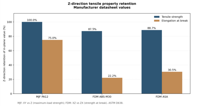
Bar chart of Z-direction retention of tensile strength and elongation for MJF PA12, FDM ABS-M30 and FDM ASA, built from datasheet values.
Is MJF Always Stronger Than FDM?
No. MJF PA12 is the stronger default for multidirectional loading than JLC3DP ABS on the published tensile figures. High-performance FDM polymers can exceed PA12 in a favorable build orientation, as the manufacturer ULTEM results in the table illustrate. That example does not establish an available JLC3DP ULTEM service. Select the material for the service environment first, then choose an orientation that carries the actual load.
Part Durability and Functional Performance
Choose ASA for prolonged sunlight and outdoor weathering, ABS for protected indoor housings, and MJF PA11 for flexible nylon features. JLC3DP reports 98°C HDT for ABS and 97.8°C for ASA; neither is a substitute for a high-temperature engineering polymer under sustained structural load. For snap-fits, control root strain. For bolted housings, allow for creep and provide inserts where repeated assembly is expected.
When to Choose MJF or FDM for Strength
Choose MJF for parts loaded in several directions and for snap-fits, clips and parts made in larger numbers. Choose FDM when a particular polymer is required, such as ULTEM or ASA, as these are not available in MJF. Also choose it when you can orient the part so the load follows the strand direction.
Accuracy, Resolution, and Surface Finish: MJF vs FDM
Dimensional Accuracy and Repeatability
JLC3DP publishes nearly the same tolerance for both: ±0.3 mm or ±0.4% for MJF, and ±0.3 mm up to 100 mm with ±0.4% above for FDM. The published figure therefore does not strongly differentiate the processes. Repeatability and failure mode do inform process selection: MJF parts shrink with build position and wall thickness, while FDM parts warp on long flat spans and small holes generally print undersize. For critical fits, specify the datum and inspection method, and plan to machine or ream.
Surface Finish and Layer Lines
FDM shows layer lines, seams and support scars. MJF has a fine, matte granular surface that is more uniform but still rough and porous. Neither is a sealing surface.
Complex Geometries, Fine Features, and Supports
JLC3DP's guidelines favor MJF for fine detail. Minimum embossed or engraved detail is 0.5 mm for MJF and 0.8 mm for FDM, and the recommended MJF wall is 1.0 mm. FDM minimum wall rises with part size: 1.6 mm at 50 × 50 mm, 2.0 mm at 100 × 100 mm and 2.5 mm at 200 × 200 mm. The JLC3DP design guideline lists the other limits.
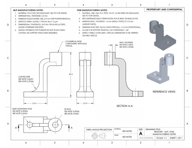
Sample part, annotations for both processes with callouts for wall thickness, small bore, unsupported roof and powder escape hole.
Post-Processing Requirements
FDM parts need support removal and often sanding or vapor smoothing. MJF parts are depowdered and bead blasted, and may be dyed. JLC3DP lists sanding, sandblasting, painting, dyeing, polishing and threaded inserts (M3, M4, M5). Define whether acceptance applies before or after finishing, because smoothing changes dimensions.
Materials and Material Properties: MJF vs FDM
MJF Materials
PA12 is the general-purpose default and PA11 adds ductility. Filled powders add stiffness at a cost: HP's glass-bead PA12 lists 30 MPa tensile strength and about 2,500 MPa modulus, against 48 MPa and 1,700 MPa for unfilled PA12. As-built parts are gray.
FDM Materials
The FDM material range includes ASA for outdoor exposure, flexible TPU and PEBA grades, carbon-fibre-filled PA12 for increased stiffness, and high-temperature polymers such as ULTEM. These options allow material selection around environmental exposure, flexibility and operating temperature, subject to the directional properties produced by the printing process.
Short carbon fibers align with the deposition path, which raises in-plane stiffness, without benefiting interlayer bonding.
Material Properties and Environmental Resistance
JLC3DP publishes ABS heat deflection of 98°C at 1.8 MPa and ASA heat deflection of 97.8°C. Their similar short-term heat-deflection figures do not erase ASA's advantage in sunlight and weathering. Choose ASA for outdoor enclosures and ABS for protected indoor functional components. Where elevated temperature dominates, evaluate a specialist high-temperature process rather than assuming standard ABS or ASA will suffice.
How to Choose a Material for Your Application
Material requirements can eliminate a process before geometry or production cost is considered. Outdoor UV exposure, repeated flexure and sustained elevated temperature each narrow the available options. Outdoor sunlight points to ASA in FDM, repeated flexing points to PA11 in MJF or TPU in FDM, and sustained heat under load points to a high-temperature FDM polymer.
Cost and Production Volume: MJF vs FDM
Equipment and Setup Costs
A basic desktop FDM printer has low acquisition cost, making it practical for immediate fit checks. Controlled industrial FDM requires more expensive equipment, ventilation and process management. MJF adds powder handling, thermal management and depowdering systems, so occasional buyers usually obtain MJF parts through a service. These are different capital-cost cases, not contradictory descriptions of the same equipment.
Cost per Part and Material Costs
JLC3DP currently advertises ABS and ASA FDM starting prices from US$3 per part. These are service entry prices, not quotations for the bracket shown in this article. Actual cost depends on the uploaded geometry, selected material, quantity, finish and production schedule. FDM often offers the cheapest simple one-off; MJF can become competitive as small parts are packed into shared builds.
One Part vs a Full Batch
For the same bracket, obtain six JLC3DP instant-quote results: FDM ABS and MJF PA12 at quantities 1, 10 and 50. Record total order price, unit price, material, finishing selection and quoted dispatch date. The original chart is an illustrative model and cannot establish a real break-even quantity. Until these six live quotations are available, do not claim that the curves cross at a particular batch size.
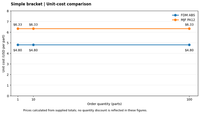
Illustrative price chart from JLC3DP instant quote service for the bracket above (JLC3DP instant quote) quantities 1, 10 and 50, FDM ABS and MJF PA12.
Build Packing and Production Efficiency
MJF parts nest in three dimensions without supports, so one build holds many differently shaped parts and shares its overhead across all of them. FDM parts sit on a plate in one layer of the build volume.
Post-Processing and Total Part Cost
Labor can outweigh printing cost, particularly in more developed (high labor cost) regions. FDM supports on a narrow channel can take longer to remove than the print took. MJF depowdering is routine, but dyeing adds a step. Machined fits add significant costs in either process.
Material Waste
HP's 80% reusability ratio for HR PA12 describes the proportion of recovered powder permitted in a powder blend; it corresponds to roughly 20% fresh-powder refresh under that specified condition. It does not mean 20% of powder is necessarily thrown away each build. FDM waste comes mainly from supports, purging and unsuccessful prints.
Ordering from a service avoids both the CAPEX and the waste handling. JLC3DP's MJF and FDM services quote online from a STEP, STL or OBJ file.
Applications and Use Cases
Rapid Prototyping and Design Validation
Choose FDM for fast, inexpensive geometry checks and simple single-part iterations. JLC3DP lists a 72–96 hour build time for ABS and 96 hours for ASA, with additional time for batch orders; these are published manufacturing times, not guaranteed delivery dates. MJF involves powder-bed scheduling, cooling and depowdering, but can consolidate many parts into one batch. Compare the quoted dispatch date for each process when schedule matters.
Functional Prototypes and End-Use Parts
MJF PA12 and PA11 are well suited to functional prototypes involving snap-fits, clips, complex housings and loads acting in multiple directions. Their relatively consistent mechanical properties across build orientations allow greater freedom in positioning features, although local wall thickness, stress concentrations and material conditioning still influence performance. PA11's higher elongation at break makes it particularly relevant to components requiring repeated elastic deformation.
FDM remains useful for functional components where a specific polymer offers an advantage. ASA provides outdoor weathering resistance, while high-temperature materials such as ULTEM 9085 extend the available operating-temperature range. Build orientation requires particular attention because tensile strength and elongation can decline substantially across deposited layers. For load-bearing parts, the print orientation should be established before evaluating the design, with critical sections assessed against the expected service loads.
Production approval introduces additional requirements for either process. Dimensional inspection should cover mounting interfaces, hole positions and other functional features, with allowance for shrinkage, warping and finishing operations. Bolted joints and snap-fits may also require testing for creep, repeated loading or environmental exposure. Where the same part will be supplied repeatedly, material grade, build parameters, orientation and inspection requirements need to remain consistent between production batches.
Complex Geometries and Lightweight Structures
MJF offers considerable geometric freedom because unfused powder supports overhangs and internal features during printing. Lattices, internal channels and closely spaced components can therefore be produced without dedicated support structures. Enclosed cavities must provide sufficient access for powder removal, however, and the specified escape holes must remain accessible after manufacture. FDM can also produce lightweight structures using controlled infill, but internal geometry is constrained by extrusion paths, bridging distances and the need to remove supports.
Low-Volume Production and Customized Parts
Runs of 10 to a few hundred parts, especially individual/unique variants, define MJF's strongest benefit, because one build easily mixes varied parts.
MJF vs FDM: Which 3D Printing Technology Should You Choose?
Multi Jet Fusion vs FDM: Decision Table by Scenario
| Scenario | Start with | Check before committing |
|---|---|---|
| Single prototype | FDM | Orientation of the critical load |
| Functional part, multi-axis load | MJF | Wall thickness and powder escape holes |
| Batch of 50 or more small parts | MJF | Quote at your exact quantity |
| Part over 370 mm | FDM | Warping on long spans |
| Complex internal geometry | MJF | Escape holes of 2.5 mm or more |
| Color or UV resistance needed | FDM | ASA or colored filament availability |
| Tight budget, one part | FDM | Whether a machined fit is also needed |
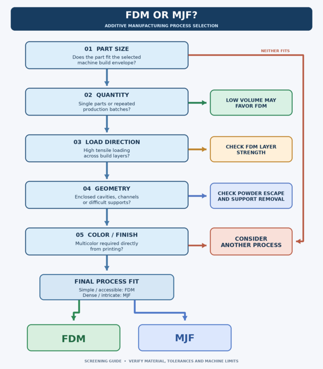
Decision flowchart: part size, quantity, load direction, geometry and color leading to FDM, MJF or another process.
Factors to Consider in FDM vs MJF 3D Printing
Choose by geometry, material environment, loading direction and quantity, then compare the quoted manufacturing lead time and price. A single large enclosure usually points to FDM; a complex nylon bracket or a batch of intricate small parts points to MJF. Shipping and finishing add to the stated build time, so use the live order quote for delivery planning.
Can You Combine MJF and FDM?
Yes. A common workflow prints early iterations in FDM, validates the design in MJF PA12 and produces the final batch in MJF. Large housings can be FDM while small functional inserts are MJF.
When to Consider Other 3D Printing Technologies
SLS gives similar nylon properties to MJF with a different powder process. SLA gives smoother surfaces for detail, and CNC machining gives tighter tolerances and metals.
FAQ about MJF vs FDM
Q: Can You Thread or Add Metal Inserts to MJF and FDM Parts?
Yes, but design the thread for the process. JLC3DP recommends M6 as the smallest printed thread, and it offers a threaded insert service for M3, M4 and M5 inserts in nylon and plastic parts. Inserts usually hold better than printed threads for repeated assembly.
Q: Which Is Better for Snap-Fits and Living Hinges, MJF or FDM?
MJF PA11 is a strong candidate. HP lists 40% elongation in XY and 25% in Z, so the hinge flexes without cracking across layers. FDM hinges work in TPU or PEBA, or in nylon printed with layers parallel to the bend.
Q: Is MJF Limited to Gray or Black Parts?
As-built MJF parts are gray, and dyeing or painting adds color. FDM offers many colors directly in the filament. For full-color parts, consider a resin process such as JLC3DP's White Jet Process.
Q: Does Carbon-Fiber FDM Match MJF Strength?
Not in all directions. Carbon-filled filaments raise in-plane stiffness, but fibers align with the deposition path, so strength across layers stays limited. MJF keeps its PA12 properties in all axes.
Q: How Large a Part Can You Order in MJF or FDM?
At JLC3DP, MJF PA12 builds up to 370 × 276 × 360 mm and ABS FDM up to 580 × 480 × 480 mm. Larger parts are split and bonded, with alignment features designed into the joint.
Conclusion: MJF vs FDM
MJF is the preferred starting point for complex nylon components, multidirectional mechanical loads and compact production batches. FDM is the preferred starting point for economical single prototypes, larger envelopes and parts requiring ABS or weather-resistant ASA. JLC3DP's own ABS and ASA data is the relevant specification for parts ordered through its FDM service. The decisive commercial comparison is the same CAD part quoted in both processes at the required quantity and finish.
Material selection can override these general advantages. ULTEM 9085, for example, reaches 69 MPa tensile strength in the specified on-edge orientation, compared with 48 MPa for MJF PA12, but falls to 42 MPa when printed upright. Production cost is similarly dependent on the actual part geometry, quantity and finishing requirements. For a functional component, the most useful comparison is between quotations for the same CAD model, supported by material data and an agreed inspection specification.
Sources and Technical References
HP, 3D High Reusability PA 12 datasheet; HP, 3D HR PA 11 and PA 12 test results; JLC3DP ABS; JLC3DP ASA; Stratasys ULTEM 9085 manufacturer datasheet; JLC3DP, 3D printing design guideline; JLC3DP, MJF materials; JLC3DP, FDM materials.
Popular Articles
Keep Learning
MJF vs FDM: Key Differences, Cost, and How to Choose the Right 3D Printing Process
Introduction HP Multi Jet Fusion powder bed on the left, FDM extrusion — the same bracket in both processes. The FDM part is a structure with locally varying density and strength — a skin filled with tessellated rigid structures that build high strength with low weight and material usage. The MJF prototype is closer to full density, less anisotropic and more uniform in structure than FDM, and has a powdery finish. MJF fuses nylon powder using selectively applied agents and infrared heat. FDM builds pa......
SLS vs SLM 3D Printing: Differences, Cost, Materials & Applications
SLS vs SLM 3D printing is often treated as a head-to-head contest, but the two processes exist for different material classes. SLS, or selective laser sintering, is mainly used to produce polymer parts. SLM, or selective laser melting, manufactures metal parts by fully melting metal powder layer by layer. For most engineering applications, the choice between SLS and SLM comes down to material requirements, mechanical performance, geometry, support structures, post-processing, lead time, and cost. This......
The Limits of 3D Printing: Comparison with Traditional Manufacturing
3D printing technology provides new solutions for the manufacturing industry in rapid prototyping, customized production and manufacturing complex geometric structures. So can 3D printing replace traditional manufacturing? Compared with traditional manufacturing processes, 3D printing still has some obvious limitations in terms of scale speed, material selection, cost efficiency, size and accuracy. This article explores the main limitations of 3D printing from several key perspectives and makes a deta......
3D Printed Articulated Animals: Design & Print Guide
Key Takeaways Design for movement first: Define how the animal should bend or move, then design joints before building the body around them. Critical dimensions matter: For FDM print-in-place joints, start with 0.2-0.3 mm clearance per side (0.4-0.6 mm total gap). Keep walls at 1.2-1.6 mm minimum, and 1.6-2.0 mm around stressed joints. Never scale functional geometry proportionally: A 0.6 mm joint gap scaled to 50% becomes 0.3 mm, falling below reliable manufacturing limits. Scale visual details, but ......
3D Printing vs CNC Service: How to Choose the Right Manufacturing Method
3D printing and CNC (Computer Numerical Control) service are two popular manufacturing methods that have gained widespread attention in recent years. 3D printing, also known as additive manufacturing, involves building 3D objects layer by layer from a digital model, while CNC service, also known as subtractive manufacturing, involves cutting away material from a solid block to create a desired shape. Both methods offer unique capabilities and advantages, and understanding their key characteristics is ......
Micro 3D Printing Explained: Technologies, Materials and Applications
Introduction Standard 3D printing builds parts you can hold in your hand. Micro Printing — and more precisely Micro 3D printing builds parts you need a magnifying glass to see, and sometimes a microscope. A microneedle array for drug delivery. A microfluidic chip with channels thinner than a human hair. A miniature optical lens with surface accuracy measured in microns. These aren't just smaller versions of parts you'd make on a standard FDM printer. They're a different category of manufacturing entir......